March 13, 2019
Now Available for Sale Here!
- Familiar and Foreign
- A Learning Experience
- The First Prototypes
- Register Maps
- MIDI, HID, and some Other Annoying Protocols
- First Notes
- Understanding the Language of Music …And Japanese
- Welcome to Register Hell
- New Voices and The OPM File Format
- Adding the PSG
- The Finishing Touches
Familiar and Foreign
Those of you that are familiar with my previous works, namely the MegaBlaster, know that I’m very much into old-school FM synthesis chips that were mainly found in 80’s/90’s arcade systems and home video game consoles. I’m pretty well-versed when it comes to playing VGM files on these old chips. The VGM format, while confusing in its own right, mostly handles all of the complicated register-specific aspects of these sound chips. Essentially, you just read-in the commands and push them to the chips without caring about what that data means. The chip knows what to do with that data so I don’t have to.
Almost immediately after I published my work on the MegaBlaster, I was asked about possibly adding MIDI functionality to it in order to use it as an instrument. At first, I was hesitant to do so – While I’m sure the MegaBlaster itself is more than capable of functioning as a MIDI device, it wasn’t really designed for that. Further still, controlling the synth chips with MIDI would require me understanding the complete ins-and-outs of each chip. It was possible, but I didn’t really think it was viable with the knowledge that I had at the time.
….Until one day where I just sucked it up and did it.
A Learning Experience
Buckle up, because this is gonna’ be a long one.
If I was going to attempt driving these ancient chips through MIDI, I was going to design a dedicated device for it, rather than shoe-horning that functionality into the MegaBlaster. This was going to be a long, multi-month learning process filled with many hours of trial and error.
First thing’s first: Which microcontroller should I use? While I love the STM32 series of BluePill boards, I figured that would be a little over-kill since I’m not dealing with the same demanding overhead requirements as playing VGM files. I really didn’t need the horsepower of 32-bit ARM and figured 8-bit AVR would be a lot easier to work with. What I really desired was native USB host support. This would make designing a MIDI device a hell of a lot easier with significantly less software pain in the long run. I settled on using the AT90USB1286 since it was the same MCU used in PJRC’s Teensy++ 2.0 boards.
While I was in the bread-boarding stage, I just used a Teensy++ 2.0. It made prototyping SO much easier since it featured just about everything I needed with a lightning-fast programming toolchain. Super handy. This would later result in a bit of pain when it came to handling proprietary bootloaders, but I’ll explain that a little later.
The First Prototypes

The first breadboard prototype
Creating the first breadboard prototype wasn’t actually all that bad. I essentially just duplicated the MegaBlaster’s analog stage and hooked up power, ground, clocks, and data lines. I was only working with the YM2612 for now as I was unsure if I even wanted to include the PSG in this design. One advantage of using AVR is the ability to directly write to 8-bit ports. Other microcontrollers can do this as well of course, but Atmel makes it super easy to do so. You may also notice a little bar of LEDs on a PCB off to the side – I designed this PCB a couple years ago. It’s just a single row of 8-LEDs and a common ground. You can hook this LED board up to 8-bit data busses and have a really quick and easy visualization of the data going across. This little board was invaluable for debugging. You could use a logic-analyzer of course, but when it comes to functional low-tech solutions, it’s hard to beat the ease-of-use and simplicity of a few blinky lights.
With the breadboard all set for testing, I needed a quick way to verify that I hooked the YM2612 up correctly. I referenced this super handy test code which replicates the “Piano Test Voice” found in the Sega Genesis’ technical manual. Both this test code and technical manual excerpt would be a godsend down the line since the official YM2612 application manual has been lost to time. After a bit of tweaking, a single channel of my YM2612 began roughly belching out a single piano tone. Good enough, let’s draw the rest of the owl.
Register Maps
Here’s where it get’s tough. First, let’s define what registers do when referring to these old sound chips. They are simply memory addresses on the chips that represent synthesizer settings. If you’ve ever seen a proper professional synthesizer keyboard, you’ve surely noticed all of the crazy knobs, switches, buttons, settings, etc. All of those sources of input are modifying the circuitry inside of the synthesizer (or values to a specific algorithm) in order to produce your custom waveform. The YM2612 et. all have lots and lots of settings to change in order to modify the final waveform and we can access those settings through the chip’s on-board registers. You can just imagine the registers as a table of values that we can change in order to make the chip do something. Indeed, this is not far off to what is really happening. Not only can you control voice (the overall sound) values, but you can also tell the chip to turn off and on specific channels or to add effects to them.
Usually, register maps are fairly straight forward. Change a value at this register address and boom, something happens. For the most part, that is true, but YM2612 is a complicated chip, so fully grasping the register system and how to write to it properly took ages. The Genesis Technical Manual I mentioned previously provided a nice starting point, but as you’ll soon see, it becomes fairly confusing and difficult to decipher without proper documentation. Before messing around with all these complicated voice register settings, the first thing I needed to do was to handle keyboard MIDI commands, and the easiest one I could think of was the “Key-On” and “Key-Off” commands.
MIDI, HID, and some Other Annoying Protocols
In order to interpret MIDI commands coming in to my prototype board, I needed a library. You could spend the time and interpret the MIDI commands manually since the protocol isn’t all that complicated, but I figured since I’d like USB MIDI support and serial MIDI support, I’d best start off not reinventing the wheel and go with something proven. Also, I didn’t want to deal with the nightmare that is HID packet interpretation. Thankfully, PJRC and the Arduino framework already provide great MIDI libraries to use free of charge. Awesome! I’ll just create my USB MIDI instance and I’ll be off!
…Or so I thought. Since the AT90USB1286 microcontroller on the Teensy was acting as an HID host, telling it to accept MIDI commands means I lost access to my invaluable serial console that I used to debug with. Not to worry, however, as you can make a few changes to the preprocessor directives of the MIDI library to get the best of both worlds. By doing this, you can have access to both USB MIDI commands and have a pseudo serial connection. Why pseudo? Well, the Teensy is actually sending your serial data through HID packets. These packets can be interpreted by the teensy_gateway.exe program included with the Teensy Framework and are broadcasted locally over Telnet to be received by any terminal client you connect to it. After adding that modification script, I wrote a little batch file that invokes the teensy_gateway program and an instance of putty to connect to it over Telnet. Boom, instant “serial” connection and USB MIDI access. You can also use the Arduino IDE’s serial console as well, but you will need to install the Teensy toolchain.
Also, if you’re using PlatformIO, be sure to tell it which build flags you’d like to use for this dual MIDI/Serial functionality.
First Notes
Okay, finally, time to make this chip sing to keyboard commands. Remember how I mentioned the “Key-On” and “Key-Off” MIDI commands? Now it was time to interpret those into commands that the YM2612 could understand. I’ll spare you the details on setting up the boilerplate MIDI side of things since it’s pretty simple and well documented (Got a MIDI command? Call X function).
Recall that the YM2612 is essentially a synthesizer hooked up to a big table of registers that control everything from voices, to effects, and most importantly, whether a key is on or off. In order to turn on a channel, we first need to provide it with a voice, then activate the Key-On register. I’ll stick with the piano test code and a single channel for now. At this stage in development, I am not concerned with pitch or how the voice sounds, I just want to be able to turn a single channel on and off through MIDI commands.
If we take a look at the register map of the YM2612, we’ll notice that register 0x28 is the Key On/Off register. This register isn’t as straight-forward as “1 in this register turns on a voice.” It’s a bit more complicated than that, but since we’re only here to test a single voice, we’ll just pass in the value 0xF0. Once we have the register/value we want to modify in mind, it’s time to tell the YM2612 what to do. Here’s where a little hardware know-how comes into play.
In order to write to the YM2612, we need to follow a strict order of operations. The YM2612 actually has two banks of nearly identical registers. You can select the upper bank by pulling the A1 pin HIGH, and the lower bank by pulling the same pin LOW. Keep this in mind for later. For now, though, the write order of operations is the following:
- Set the A1 pin for the register bank you want to access
- Set A0 to LOW
- Set Chip Select (CS) to LOW
- Write the address of the register you’d like to access to the 8-bit bus
- Set WR to LOW
- Wait a microsecond
- Set WR, CS, and A0 back to HIGH to finish the address write
- Pull CS down to LOW again since we need to write the data now
- Write your new register value to the 8-bit bus
- Set WR to LOW yet again and wait a microsecond like last time
- Set WR and CS back to HIGH to finish the data write
- Set A1 and A0 back to LOW to prepare for next time
Sound like a pain in the ass? That’s because it is! You can see an example of my YM2612 “send” function where I’ve implemented the above procedure here:
void YM2612::send(unsigned char addr, unsigned char data, bool setA1)
{
    digitalWriteFast(_A1, setA1);
    digitalWriteFast(_A0, LOW);
    digitalWriteFast(_CS, LOW);
    PORTC = addr;
    digitalWriteFast(_WR, LOW);
    delayMicroseconds(1);
    digitalWriteFast(_WR, HIGH);
    digitalWriteFast(_CS, HIGH);
    digitalWriteFast(_A0, HIGH);
    digitalWriteFast(_CS, LOW);
    PORTC = data;
    digitalWriteFast(_WR, LOW);
    delayMicroseconds(1);
    digitalWriteFast(_WR, HIGH);
    digitalWriteFast(_CS, HIGH);
    digitalWriteFast(_A1, LOW);
    digitalWriteFast(_A0, LOW);
}
With ALL of this in mind, I can finally toggle a single channel through MIDI. Using the MIDI library, any time I receive a Key On command, I’ll simply call my YM2612 ‘send()’ function and write 0xF0 to register 0x28. Once I receive a Key Off command, I’ll send over the value 0x00 to clear register 0x28 which will tell the synth to being the “decay” of the voice.
ym2612.send(0x28, 0xF0, 0); //Reg 0x28, Value 0xF0, A1 LOW. Key On
ym2612.send(0x28, 0x00, 0); //Reg 0x28, Value 0xF0, A1 LOW. Key Off
Writing to the registers like this will be the basis of everything we do moving forward. It only becomes more complicated from here on out!
Understanding the Language of Music …And Japanese
So I’ve got a box that goes ‘bing’ and that’s about it. No chords, no other voices, not even any other notes. How can we take in MIDI Key-On commands and translate them into properly tuned notes that represent the keys you’re pressing? By doing a shit ton of annoying math. You see, instead of just pushing over your desired frequency to some arbitrary register and just letting the chip figure it out, you have to compute something known as the “F-Number.” This F-Number is what’s sent to the F-Number register and is what determines the output frequency of your note. Okay, where can we find the formula for this F-Number? In the YM2612 Application Manual! ….that doesn’t exist. Aw.
But, fortunately for me, the YM2612 has a twin CMOS sister, the YM3438, AKA the OPN2c. These two chips are functionally identical and share the same register map, the only real difference being the output stage. A manual does in fact exist for the YM3438, and you can find it here. Unfortunately for us, it’s entirely in Japanese.
Well as it turns out I can read Japanese just fine so we’re good.
Anyways, let’s get to what we need. The F-Number. On page 23 and 24, you can see information related to the F-number, as well as a little register map showing where that value should eventually end up. The formula for calculating the F-number is:
(144 × fnote × 220 ÷ fM) ÷ 2(B-1)
fnote = Your desired note frequency
fM = The frequency of your master clock
B = Block number
Okay, not the worst formula ever, but for little microcontrollers with no floating point units, this is kind of a nightmare. Let’s try and compute an F-number for note A4, just like the application manual does.
The frequency of an A4 note is 440 Hz. Our master clock frequency is 8MHz (8,000,000 Hz). The block number is… wait, damn it, block number?
Yep, yet another gotcha. As you move up the musical scale, your block number will change. The block number is a 3-bit value that basically represents which octave you’re on. If you compute a table for a single octave, you can use the block number to shift that table up and down for each octave instead of computing the F-numbers each time. For the sake of this example, let’s assign it to 4 (Get it? A4 is in block 4!).
(144 × fnote × 220 ÷ fM) ÷ 2(B-1)
fnote = 440
fM = 8000000
B = 4
FNum = (144 × 400 × 220 ÷ 8000000) ÷ 2(4-1)
FNum = 1038.09024
And if we look at the example table in the YM3438 manual…

Perfect! Exactly what we were looking for.
Now, every time we receive a MIDI command, we can grab the key number, convert it to its frequency using some more math, then convert that frequency into our F-Number using the formula above. Don’t forget the block number calculation too!
You’re not done yet. Now you have to pack all of that information into a byte and send it out to each channel’s frequency register! I’ll spare you the details here and have you look the source code for that one. Since this was such a computational nightmare, I scoured the web for more elegant solutions that used LUTs (Look-up tables) instead and discovered a master-class solution by Diego Dorado.
I incorporated a similar design into my final project since it supported pitch bending better, but before I discovered, I did all of the math on the fly.
No polyphony yet, just one dinky FM piano voice and a single key at a time, but it was progress.
Welcome to Register Hell
AHHHHHHHHHH
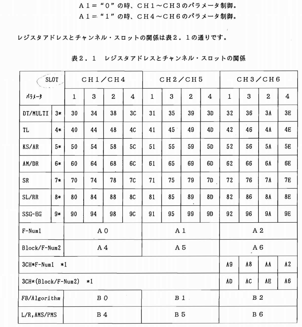
Monophony was pretty tricky, but polyphony was going to be an even bigger nightmare. The image above is the complete memory map of the OPN (YM2612/YM3438). Understanding this map requires a keen eye in pattern recognition and a mountain of patience for cryptic and unhelpful application notes (in a foreign language!). Oh and did I mention: pulling A1 HIGH will swap you over to another identical bank of registers for the upper 3 channels that you must also set. Goodie.
Quickly take a look at that register map and see if you can spot any obvious patterns. To me, the first one that stands out is that each address along the Y axis is spaced out by 0x10. This is handy to keep in mind as we will use it to quickly iterate through each address. Also remember that since we can jump up to the upper register bank that controls channels 4, 5 and 6 using pin A1, the register addresses are identical but the values are not! Also, notice along the X-axis, each address seems to be spaced out by 0x04. Why? There are four operators per channel! (The manual refers to channels as “slots,” by the way.)
Let’s hop waaaaaay back into my code when I first implemented polyphony.
Take a look at the setup() function. You can see that I first generate a LUT for F-numbers using GenerateNoteSet(), then perform a little housekeeping to set the clocks and such.
But then you will notice this block:
  ym2612.send(0x22, 0x00); // LFO off
  ym2612.send(0x27, 0x00); // CH3 Normal
  ym2612.send(0x28, 0x00); // Note off (channel 0)
  ym2612.send(0x28, 0x01); // Note off (channel 1)
  ym2612.send(0x28, 0x02); // Note off (channel 2)
  ym2612.send(0x28, 0x04); // Note off (channel 3)
  ym2612.send(0x28, 0x05); // Note off (channel 4)
  ym2612.send(0x28, 0x06); // Note off (channel 5)
  ym2612.send(0x2B, 0x00); // DAC off
Right here, I am simply turning off the Low-Frequency Oscillator (LFO), setting Channel 3 to it’s “normal” mode, sending a Key-Off command to each channel, and finally, disabling the Digital to Analog Converter (DAC). This is just a bit of setup code that prepares the YM2612 without having it digitally scream at us.
The main part of this function is where I actually set the piano test voice for every channel:
  for(int a1 = 0; a1<=1; a1++)
  {
    for(int i=0; i<3; i++)
    {
          //Operator 1
          ym2612.send(0x30 + i, 0x71, a1); //DT1/Mul
          ym2612.send(0x40 + i, 0x23, a1); //Total Level
          ym2612.send(0x50 + i, 0x5F, a1); //RS/AR
          ym2612.send(0x60 + i, 0x05, a1); //AM/D1R
          ym2612.send(0x70 + i, 0x02, a1); //D2R
          ym2612.send(0x80 + i, 0x11, a1); //D1L/RR
          ym2612.send(0x90 + i, 0x00, a1); //SSG EG

          //Operator 2
          ym2612.send(0x34 + i, 0x0D, a1); //DT1/Mul
          ym2612.send(0x44 + i, 0x2D, a1); //Total Level
          ym2612.send(0x54 + i, 0x99, a1); //RS/AR
          ym2612.send(0x64 + i, 0x05, a1); //AM/D1R
          ym2612.send(0x74 + i, 0x02, a1); //D2R
          ym2612.send(0x84 + i, 0x11, a1); //D1L/RR
          ym2612.send(0x94 + i, 0x00, a1); //SSG EG

         //Operator 3
          ym2612.send(0x38 + i, 0x33, a1); //DT1/Mul
          ym2612.send(0x48 + i, 0x26, a1); //Total Level
          ym2612.send(0x58 + i, 0x5F, a1); //RS/AR
          ym2612.send(0x68 + i, 0x05, a1); //AM/D1R
          ym2612.send(0x78 + i, 0x02, a1); //D2R
          ym2612.send(0x88 + i, 0x11, a1); //D1L/RR
          ym2612.send(0x98 + i, 0x00, a1); //SSG EG

         //Operator 4
          ym2612.send(0x3C + i, 0x01, a1); //DT1/Mul
          ym2612.send(0x4C + i, 0x00, a1); //Total Level
          ym2612.send(0x5C + i, 0x94, a1); //RS/AR
          ym2612.send(0x6C + i, 0x07, a1); //AM/D1R
          ym2612.send(0x7C + i, 0x02, a1); //D2R
          ym2612.send(0x8C + i, 0xA6, a1); //D1L/RR
          ym2612.send(0x9C + i, 0x00, a1); //SSG EG

          ym2612.send(0xB0 + i, 0x32); // Ch FB/Algo
          ym2612.send(0xB4 + i, 0xC0); // Both Spks on
          ym2612.send(0xA4 + i, 0x22); // Set Freq MSB
          ym2612.send(0xA0 + i, 0x69); // Freq LSB
    }
  }
  ym2612.send(0xB4, 0xC0); // Both speakers on
  ym2612.send(0x28, 0x00); // Key off
There are two loops. A loop with an iterator that represents A1 and i that represents a single channels specific register index. As I loop the first time, a1 is set to 0, meaning I keep the A1 pin set to LOW. We’ve selected the lower bank of registers. We then iterate through all of the voice setting registers, one by one, and place our test piano voice values inside of them. We do this three times, as there are three channels on the lower bank. Once we loop three times, we increment a1 by 1. Pin A1 is now pulled HIGH, so we are now on the upper register bank. Recall that the addresses in each register bank are identical, so we just iterate over all of the same addresses with the same data yet again, this time for channels 4, 5, and 6. Finally, I activate both the left and right speaker outputs by writing 0xC0 to address 0xB4 and made sure that the “Key-down” register was reset to 0x00.
Are we ready for polyphony yet? Haha, no.
We’ve only just set the register’s voice values. Meaning, were this a real standalone synthesizer keyboard, we just set all the knobs and dials to their correct settings. In order to produce polyphony, we still need to tell the YM2612 which channels are on, which channels are off, and at what frequency each channel is supposed to be set to.
In order to spare you from another math onslaught, I figured it’s probably best for you to see the old project code itself.
In a nutshell, I kept track of how many keys were being pressed on. The YM2612 only has 6 channels, so a maximum of six keys could be pressed at a time. Every time a key was pressed, I would check to see how many other keys were pressed and assign the note a channel after performing the F-number, Block number, etc. calculations. If the channel assigned was 4, 5, or 6, I had to set pin A1 to HIGH so I could select the upper register. To handle a key-off event, I simply referenced which channels were assigned which MIDI note number when they were turned on and would simply reverse the process (without having to calculate for F-Number, of course).
void KeyOn(byte channel, byte key, byte velocity)
{
  uint8_t offset, block, msb, lsb;
  uint8_t openChannel = ym2612.SetChannelOn(key);
  offset = openChannel % 3;
  block = key / 12;
  key = key % 12;
  lsb = fNumberNotes[key] % 256;
  msb = fNumberNotes[key] >> 8;

  bool setA1 = openChannel > 2;

  if(openChannel == 0xFF)
    return;

  Serial1.print("OFFSET: "); Serial1.println(offset);
  Serial1.print("CHANNEL: "); Serial1.println(openChannel);
  Serial1.print("A1: "); Serial1.println(setA1);
  ym2612.send(0xA4 + offset, (block << 3) + msb, setA1);
  ym2612.send(0xA0 + offset, lsb, setA1);
  ym2612.send(0x28, 0xF0 + offset + (setA1 << 2));
}

void KeyOff(byte channel, byte key, byte velocity)
{
  uint8_t closedChannel = ym2612.SetChannelOff(key);
  bool setA1 = closedChannel > 2;
  ym2612.send(0x28, 0x00 + closedChannel%3 + (setA1 << 2));
}
I kept track of all the note channel assignments in the YM2612 driver. Prototype code is messy!
But hey, look! Full six-channel polyphony! Yay, we’ve made a budget-conscious, early-90’s toy keyboard!
New Voices and The OPM File Format
So we’ve got basic polyphony, but we’re still using the same lame piano test voice. The ultimate goal of this project is to be able to play any instrument from any Sega Genesis soundtrack. Now we already know that there are a whole host of complicated registers that we can set to control all of the intricate details that go into crafting each FM voice. If we wanted to, we could go in manually using a Sega emulator, scope out all of the individual memory addresses that make up each voice, and push those values one-by-one into the YM2612’s voice registers. If you really don’t value your time and want to do something mind numbing, this is the route for you.
Fortunately for us, there is indeed an easier solution. The OPM file format.
While the OPM file format was originally designed for… well.. the OPM FM synthesizer chip (AKA, YM2151), we can use it to also program our YM2612’s. Since the YM2612 and the YM2151 are so similar, the voice registers are practically identical. Originally, this file format was designed to be used with VOPM, the YM2151 VST that can also be used to craft custom patches for our final synth project. We can also convert .VGM files to OPM files with ease using a tool that I’ll talk about a little later. OPM files perfectly map out all of the register settings to give us the exact voices we need to replicate those found in Sega Genesis games. The downsides? The format itself is really poorly documented, and since it’s text-based, it’s kind of a pain to parse.
How do we get YM2612 OPM files? Glad you asked, because I have a package of practically every YM2612 OPM voice file available. You’d be hard-pressed to not find a game track in this pack. You can download the YM2612 OPM files here.
Can’t find your game’s patch listed in that archive but you have the VGM file? Don’t worry, I’ve got a tool for you here! Simply follow the directions in the readme file and you should be all set. This should make converting VGM files to OPM super easy.
Now that we’ve got our OPM patch files, let’s explore the format a little bit and see how I applied them to my YM2612. Since OPM files are text-based, you can open them up in a text editor and see all of the individual voice settings. (You can also manually tweak these voice settings in a text editor too, if you know what you’re doing)
Once we open up an OPM file, you will see all of the individual instrument patches. They look like this:
@:0 Instrument 0
LFO: 0 0 0 0 0
CH: 64 6 6 0 0 120 0
M1: 31 18 0 15 15 24 0 15 3 0 0
C1: 31 17 10 15 0 18 0 1 3 0 0
M2: 31 14 7 15 1 18 0 1 3 0 0
C2: 31 0 9 15 0 18 0 1 3 0 0
If we take a look at the anemic specification and compare it to the YM2612 register documentation, we can slowly work out what all of these settings mean. Here’s what the specification says:
@:voice_num voice_title
LFO: LFRQ AMD PMD WF NFRQ
CH: PAN FL CON AMS PMS SLOT NE
M1: AR D1R D2R RR D1L TL KS MUL DT1 DT2 AME
C1: AR D1R D2R RR D1L TL KS MUL DT1 DT2 AME
M2: AR D1R D2R RR D1L TL KS MUL DT1 DT2 AME
C2: AR D1R D2R RR D1L TL KS MUL DT1 DT2 AME
At the top, you will see an @ symbol, a colon :, a voice number, and the instrument number. These headers are standardized, so we can use them to know which voice we’re looking at. Next, let’s look at the LFO: CH: M1:, C1:, M2:, C2: parameters.
LFO stands for Low Frequency Oscillator. When dealing with standard YM2612 OPMs, these values are always zero. CH is used for global channel algorithm settings that affect every operator at once. M1, C1, M2, and C2 are the names of the 4 operators within every synth channel. If we’re creating a polyphonic, mono-timbral synth, we need to set every channel’s 4 operators with the exact same data. Don’t confuse operators with channels. There are six individual channels, each with their own set of four operators, meaning there are 24 operators in total to set.
Let’s define what all of the OPM settings stand for. Every value is in decimal, not hex.
LFO: Low Frequency Oscillator Settings (Usually all 0)
LFRQ: LFO Frequency
AMD: Amplitude Modulation Enable
PMD: Phase Modulation
WF: Waveform
NFRQ: eNable Low Frequency Oscillator
CH: Channel Algorithm Settings
PAN: Panning? This setting is unknown and is unused.
FL: Feedback Loop
CON: Connection, AKA "Algorithm"
AMS: Amplitude Modulation Sensitivity
PMS: Phase Modulation Sensitivity (AKA Frequency Modulation Sensitivity)
SLOT: Slot Mask
NE: Noise Enable. Unused in our case.
Operators: M1, C1, M2, C2
AR: Attack Rate
D1R: Decay Rate 1
D2R: Decay Rate 2
RR: Release Rate
D1L: Decay Level 1
TL: Total Level
KS: Key Scaling
MUL: Multiplier
DT1: Fine Detuning
DT2: Coarse Detuning
AME: Amplitude Modulation Enable
If you take a look at the register map for the YM2612, you’ll find lots of these settings in there. Essentially, all we have to do is read-in these OPM file settings and transfer them over to the appropriate YM2612 registers. Making a plain-text file parser is always a bit of a nightmare, and I’m completely positive there is a better way to do this, but I’ve developed a function that seems to parse OPM files perfectly fine.
First, I create a struct to store my voice data, as well as an array of voices since each OPM file will contain multiple different voices. Each instrument you hear in a Sega Genesis music track (with the exception of PCM samples), will have it’s own voice patch.
Once I have my “voice” struct array, I then populate it with the following function:
void ReadVoiceData()
{
  size_t n;
  uint8_t voiceCount = 0;
  char * pEnd;
  uint8_t vDataRaw[6][11];
  const size_t LINE_DIM = 60;
  char line[LINE_DIM];
  while ((n = file.fgets(line, sizeof(line))) > 0)
  {
      String l = line;
      //Ignore comments
      if(l.startsWith("//"))
        continue;
      if(l.startsWith("@:"+String(voiceCount)+" no Name"))
      {
        maxValidVoices = voiceCount;
        break;
      }
      else if(l.startsWith("@:"+String(voiceCount)))
      {
        for(int i=0; i<6; i++)
        {
          file.fgets(line, sizeof(line));
          l = line;
          l.replace("LFO: ", "");
          l.replace("CH: ", "");
          l.replace("M1: ", "");
          l.replace("C1: ", "");
          l.replace("M2: ", "");
          l.replace("C2: ", "");
          l.toCharArray(line, sizeof(line), 0);

          vDataRaw[i][0] = strtoul(line, &pEnd, 10);
          for(int j = 1; j<11; j++)
          {
            vDataRaw[i][j] = strtoul(pEnd, &pEnd, 10);
          }
        }

        for(int i=0; i<5; i++) //LFO
          voices[voiceCount].LFO[i] = vDataRaw[0][i];
        for(int i=0; i<7; i++) //CH
          voices[voiceCount].CH[i] = vDataRaw[1][i];
        for(int i=0; i<11; i++) //M1
          voices[voiceCount].M1[i] = vDataRaw[2][i];
        for(int i=0; i<11; i++) //C1
          voices[voiceCount].C1[i] = vDataRaw[3][i];
        for(int i=0; i<11; i++) //M2
          voices[voiceCount].M2[i] = vDataRaw[4][i];
        for(int i=0; i<11; i++) //C2
          voices[voiceCount].C2[i] = vDataRaw[5][i];
        voiceCount++;
      }
      if(voiceCount == MAX_VOICES-1)
        break;
  }
  Serial.println("Done Reading Voice Data");
}
Those who are more gifted in C-string manipulation than I am are probably wincing a little right now, but this function works perfectly, so I think I’ll keep it. This function will also automatically detect when there are no more valid voices to read in since the OPM format likes to generate way more voice blocks than are actually available. Brilliant format, right? But hey, it’s what we’ve got to work with.
Now here’s the tricky part. If we take a peek through the YM2612’s register map, you’ll notice that several register settings are actually packed together into a single byte. This is the late 80’s/early 90’s after all, and storage space is at a premium! No worries, though. A bit of careful bitwise scrunching of our otherwise organized voice data is all we need. Once we’ve packed everything into their appropriate bytes, we can send our new fancy voice register data over to the YM2612 just like we did with the old piano test voice.
void YM2612::SetVoice(Voice v)
{
  currentVoice = v;
  bool resetLFO = lfoOn;
  if(lfoOn)
    ToggleLFO();
  send(0x22, 0x00); // LFO off
  send(0x27, 0x00); // CH3 Normal
  for(int i = 0; i<7; i++) //Turn off all channels
  {
    send(0x28, i);
  }
  send(0x2B, 0x00); // DAC off

  for(int a1 = 0; a1<=1; a1++)
  {
    for(int i=0; i<3; i++)
    {
          uint8_t DT1MUL, TL, RSAR, AMD1R, D2R, D1LRR = 0;

          //Operator 1
          DT1MUL = (v.M1[8] << 4) | v.M1[7];
          TL = v.M1[5];
          RSAR = (v.M1[6] << 6) | v.M1[0];
          AMD1R = (v.M1[10] << 7) | v.M1[1];
          D2R = v.M1[2];
          D1LRR = (v.M1[4] << 4) | v.M1[3];

          send(0x30 + i, DT1MUL, a1); //DT1/Mul
          send(0x40 + i, TL, a1); //Total Level
          send(0x50 + i, RSAR, a1); //RS/AR
          send(0x60 + i, AMD1R, a1); //AM/D1R
          send(0x70 + i, D2R, a1); //D2R
          send(0x80 + i, D1LRR, a1); //D1L/RR
          send(0x90 + i, 0x00, a1); //SSG EG

          //Operator 2
          DT1MUL = (v.C1[8] << 4) | v.C1[7];
          TL = v.C1[5];
          RSAR = (v.C1[6] << 6) | v.C1[0];
          AMD1R = (v.C1[10] << 7) | v.C1[1];
          D2R = v.C1[2];
          D1LRR = (v.C1[4] << 4) | v.C1[3];
          send(0x34 + i, DT1MUL, a1); //DT1/Mul
          send(0x44 + i, TL, a1); //Total Level
          send(0x54 + i, RSAR, a1); //RS/AR
          send(0x64 + i, AMD1R, a1); //AM/D1R
          send(0x74 + i, D2R, a1); //D2R
          send(0x84 + i, D1LRR, a1); //D1L/RR
          send(0x94 + i, 0x00, a1); //SSG EG

          //Operator 3
          DT1MUL = (v.M2[8] << 4) | v.M2[7];
          TL = v.M2[5];
          RSAR = (v.M2[6] << 6) | v.M2[0];
          AMD1R = (v.M2[10] << 7) | v.M2[1];
          D2R = v.M2[2];
          D1LRR = (v.M2[4] << 4) | v.M2[3];
          send(0x38 + i, DT1MUL, a1); //DT1/Mul
          send(0x48 + i, TL, a1); //Total Level
          send(0x58 + i, RSAR, a1); //RS/AR
          send(0x68 + i, AMD1R, a1); //AM/D1R
          send(0x78 + i, D2R, a1); //D2R
          send(0x88 + i, D1LRR, a1); //D1L/RR
          send(0x98 + i, 0x00, a1); //SSG EG

          //Operator 4
          DT1MUL = (v.C2[8] << 4) | v.C2[7];
          TL = v.C2[5];
          RSAR = (v.C2[6] << 6) | v.C2[0];
          AMD1R = (v.C2[10] << 7) | v.C2[1];
          D2R = v.C2[2];
          D1LRR = (v.C2[4] << 4) | v.C2[3];
          send(0x3C + i, DT1MUL, a1); //DT1/Mul
          send(0x4C + i, TL, a1); //Total Level
          send(0x5C + i, RSAR, a1); //RS/AR
          send(0x6C + i, AMD1R, a1); //AM/D1R
          send(0x7C + i, D2R, a1); //D2R
          send(0x8C + i, D1LRR, a1); //D1L/RR
          send(0x9C + i, 0x00, a1); //SSG EG

          uint8_t FBALGO = (v.CH[1] << 3) | v.CH[2];
          send(0xB0 + i, FBALGO, a1); // Ch FB/Algo
          send(0xB4 + i, 0xC0, a1); // Both Spks on

          send(0x28, 0x00 + i + (a1 << 2)); //Keys off
    }
  }
  if(resetLFO)
    ToggleLFO();
}
And the result: A little rough around the edges, but hey! Listen to that! Actual voice patches from Genesis games!
Adding the PSG
Once I was happy with how my YM2612 was turning out, I made the decision to also include the PSG. While PSG synths have been done to death, I figured my project wouldn’t be a “complete” Genesis synth without including it. I assumed since the PSG was just a simple 3-channel square wave synth, it should be much easier to implement than the YM2612.
Weeeeeeellllll….
The SN76489 Programmable Sound Generator is an ancient chip. This IC was first minted in the late 1970’s, so writing to the chip is kind of a pain. The convoluted method involved in writing to this chip makes pitch-bending fairly difficult as well.

Big-Endian. Yuck.
First, let’s focus on how we can transfer data over to the PSG. This part is actually fairly straight forward, especially compared to the YM2612.
- Make sure the WE pin is set HIGH
- Send your byte over the 8-bit data bus
- Set WE to LOW
- Wait 14 microseconds to let the PSG process that data
- Pull WE HIGH again to complete the write
Technically, step 4 is kind of faux pas, since there is a dedicated READY pin on the IC that will go HIGH once the IC has completed it’s data transaction, but since the IC consistently completes writes within the same amount of clock cycles, it’s not entirely necessary. If you do decide to go with the READY pin instead of waiting 14 microseconds, the READY pin is open-drain and needs to be pulled-up with an external 2K resistor to 5V. The internal 10K pull-ups that are normally found on microcontrollers will not work as they are too weak for the PSG.
void SN76489::send(uint8_t data)
{
    //Byte 1
    // 1   REG ADDR        DATA
    //|1| |R0|R1|R2| |F6||F7|F8|F9|

    //Byte 2
    //  0           DATA
    //|0|0| |F0|F1|F2|F3|F4|F5|

    digitalWriteFast(_WE, HIGH);
    PORTC = data;
    digitalWriteFast(_WE, LOW);
    delayMicroseconds(14);
    digitalWriteFast(_WE, HIGH);
}
Much like the YM2612, there is also a formula required to calculate the data found in the PSG’s frequency register. Thankfully though, this equation is much simpler:
F = N ÷ (32 × n)
F = Desired PSG Frequency
N = Master Clock Frequency
n = Desired Note Frequency (10-bit number)
Let’s calculate for note A4 again using the above equation:
F = 4000000Hz ÷ (32 × 440Hz)
F = 284.1
Again, this part is pretty simple.
Once you have that value, you can send it to the PSG using the following method:
void SN76489::SetSquareFrequency(uint8_t voice, int frequencyData)
{
    if (voice < 0 || voice > 2)
        return;
    send(0x80 | frequencyRegister[voice] | (frequencyData & 0x0f));
    send(frequencyData >> 4);
}
Where it gets super annoying though, is when you have to account for pitch bending. That required a lot more math. You can view the entire PSG driver script here if you’re interested in seeing how it was done.
This video also shows the project after I had implemented hardware serial MIDI.
The Finishing Touches

Don’t judge. It worked perfectly.
All that was really left was a bit of trial-and-error tuning, adding a MIDI circuit, and then finally producing a printed circuit board. I also ditched the buck-converter I was using to knock 12V down to 5V in favor of a linear regulator since the buck converted produced quite a bit of audible noise. In order to test the PCB heat-sinking performance of said regulator, I decided to sacrifice one of my (silly) TQFP-64 to DIP boards and solder the regulator to the ground plane that I exposed by sanding off the solder mask.
Another thing I wanted to test is to see if I could run my code on a bare AT90USB1286 microcontroller without the use of PJRC’s proprietary HalfKay bootloader. With a bit of fiddling on a demo board, yes indeed, I can run my code without the bootloader. I just have to upload the code every time using an ATMEL ICE, or any other ISP (In-circuit Serial Programmer). I also switched from using LTC6904s for my clock generators to discrete crystal pierce oscillators. They’re far more accurate, cheaper, and easier to use.

My AT90USB1286 Test Board
I also added a rotary encoder and a 20×04 character LCD to act as the user interface. All that was left was to plot the schematic and design the PCB.

The schematic
The final breadboard prototype looked like this monster: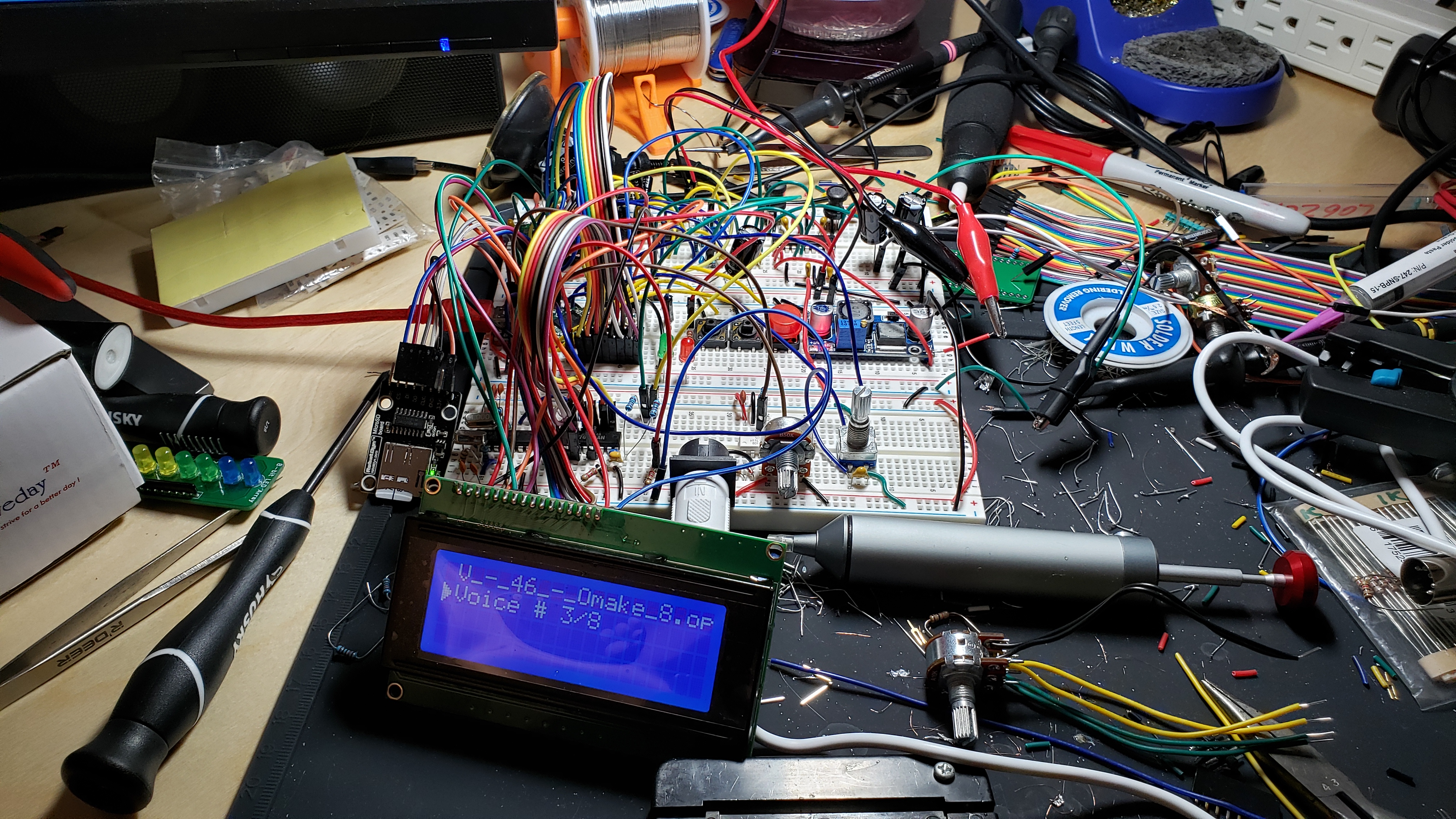
Finally, it was time to jump into the KiCAD PCB Editor and design a board. I wanted a relatively compact board, around 100x100mm that had a rotary encoder, several “favorite patch” buttons, and a way to mount my LCD above the assembly. This took a lot of research, measuring, and double-checking. Once I got the boards made, the quality was good and the screen mounted perfectly with 15mm nylon standoffs and 21mm header pins. …Only problem is that I pulled the LCD’s data R/W pin to VCC when it should have been GND. Darn, so close to perfect. Oh well, I just cut the lead and stretched it over to my GND test point. The Op-amp also had an issue – KiCAD didn’t recognize that pin 4 and pin 8 were part of the netlist, so the DRC overlooked them and didn’t tell me they weren’t connected. Damn. A couple of bodges later though, and we were all patched up.
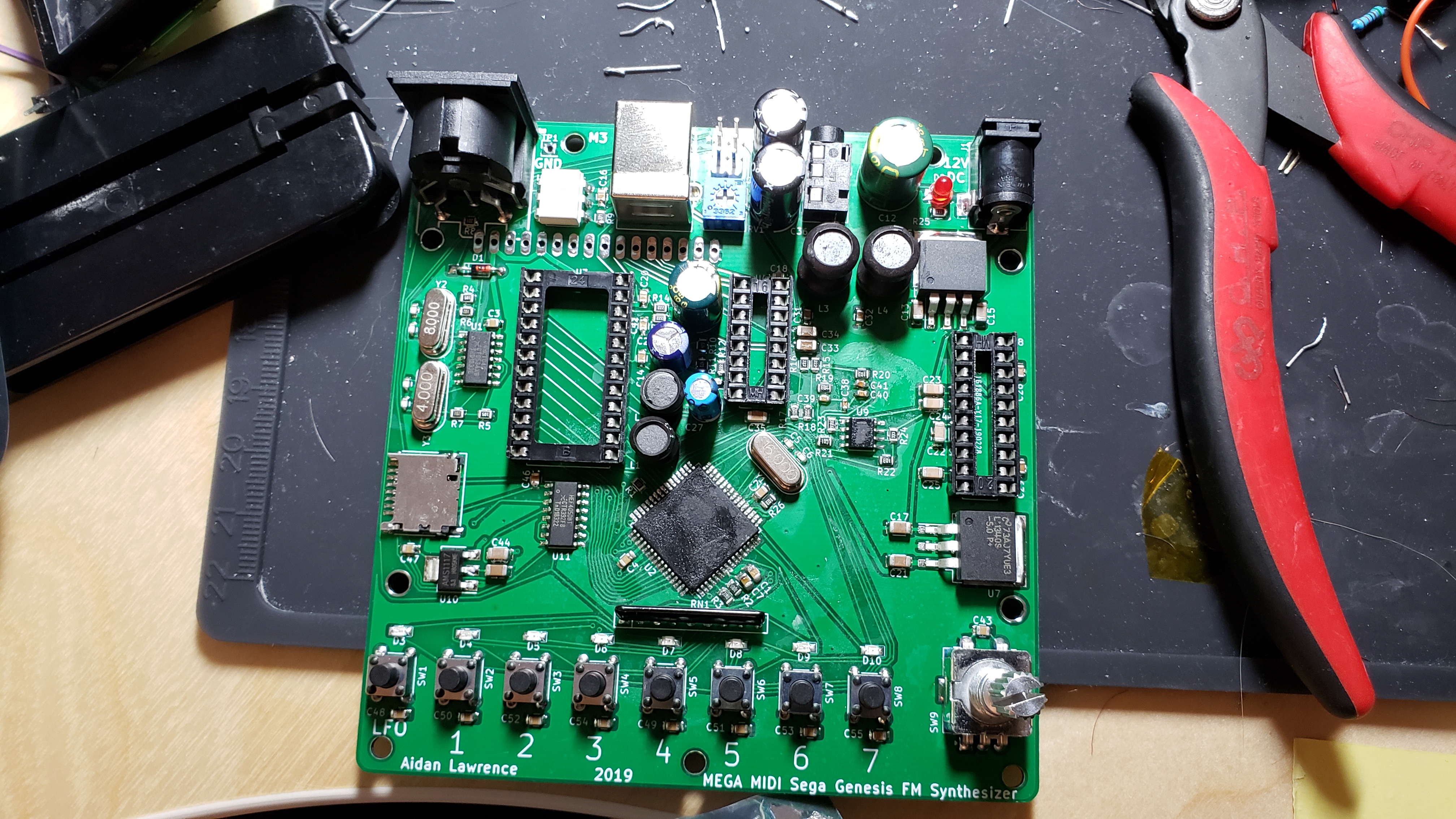
Here’s the board without the LCD or chips installed yet.
I also needed to turn off the JTAG fuse on the new AT90USB1286. This gave me a mini heart attack since it was preventing the main data bus from operating correctly. I thought I was screwed, but all I had to do was change the fuses to:
EXTENDED: 0xF3
HIGH: 0xDF
LOW: 0x5E
Phew.
Once it was all said and done, I polished the unit up and recorded my first video on it! (Top of the page)
All that’s left is to modify the board a little bit to remove the bodged connections. I also want to transition to as many surface-mounted parts as possible as it will likely speed up production times.
GUH! That was a lot and it was only a very high-level overview. In reality, this entire process took many long months. If you actually did read all of this, thank you very, very much! I appreciate your interest in the project! Feel free to look through the source material. Once version 2 is complete, I will release the KiCAD PCB files.

Hi Aidan,
I am impressed with your work on this, interestingly, this is much along the lines of what I would like to do as a project and the timing of your release is quite a coincidence that I have been buying bits on ebay from china for a good few weeks. I had already found your Megablaster and was planning to use some of the code you had developed on that to get a midi instrument working, however, unlike either project (although I do like the YM2612) I was thinking of the YM2608 (a brave choice and now I realise, perhaps a foolish one, I can’t even fit it in a proto-board). Or the OPL2.
I wonder what your opinion is on driving either of those chips’ registers? I did buy some YM3438s too, in case.
I have picked up some STM32s also, not so much because they are sized well for the job, they are technically overkill except for IO on the blue/black pills but because they are very economic and they offer the possibility of fast maths to do more of the instrument functions as well as midi. I am thinking of procedural sequence generation, dynamic operators/envelopes, and more traditional sequencing.
I am just learning to code MCUs but can read your code reasonably easily, so far I think, and your notes about how it works are very helpful.
So far I have found the Midibox Quad Genesis, which is a bit complex/bonkers, and this thing:
https://www.youtube.com/watch?v=jf10Ta8NnUc
which is similar to what you are developing.
Incidentally, what environment do you code STM32 in? I have Arduino IDE up and running, but suspect it is possibly one of the least efficient coding platforms for STM32.
In the meantime, thanks for recording your progress, the information here is quite insightful, especially as my Japanese is limited to foodstuffs.
All the Best,
Matt
Pingback: And Everything Inbetween – Aidan Lawrence
Hi Adian,
Excellent project, nice work!
I picked up a YM3436 last week (akihabara gachapon kadenken) and I would love to build a project like yours.
Is there a chance I could get one you your PCBs?
Weiman
Small world, I was just at that same shop the other day and had a good time chatting with the owner. The MegaMIDI board is still being revised, so I’ll release an open-sourced version of the KiCAD files once I’m back from Japan.
I found the shop via strange parts actually :)
It’s nice to read that you really clicked with the shop owner. It’s rare to geek out at that level (even at uni / work).
I cannot wait for your new version!
What a great read! I would absolutely buy one of these boards if they were available.
I’d even be really happy to take a stab making the patches editable on the board as well. How difficult is it to tell the chip to change between operator values on the fly (rather than via OPM files)? It would be amazing to create new patches on the fly after hearing how chip responds to certain values.
Apologies if this shows up twice, I wasn’t sure if I posted my initial comment.
Thanks for stopping by and giving the article a read. These boards will be up for sale soon – I’m preparing them as I type this!
Patches can’t be edited “on the fly” right now mainly because I’d like the barrier to entry for this project to be as low as possible.
Creating FM patches manually is really, really tough and time consuming. Though, what you can do, is use the VOPM virtual synth to create patches, then export
the OPM file and play those patches on the Mega MIDI.
Hiya, Are these available to buy and how much
Hello Stephen,
They are available for purchase! You can buy the latest version of the Mega MIDI here https://www.aidanlawrence.com/product/mega-midi-5/