December 7, 2017

Hardware Sega Genesis Video Game Music Player 3.0

All soldered together with new features and 50% more groove

So Much Soldering...

After creating two (V1 / V2) breadboard prototypes of my Sega Genesis / Megadrive Video Game Music Player, I decided it was finally time to get this project all soldered up. The breadboard prototypes worked fine for the most part when it came to the digital side of things, but on the analogue side, the finicky and unstable connections really hampered the quality and reliability of the project as a whole. I considered manufacturing a custom printed circuit board for this project, but ultimately decided against it due to the cost of spinning up a huge board that would require several layers. Instead, I opted for some cheap perfboard that I imported from China. This would allow me to keep my familiar breadboarding layout but give me the performance of a soldered-together project.

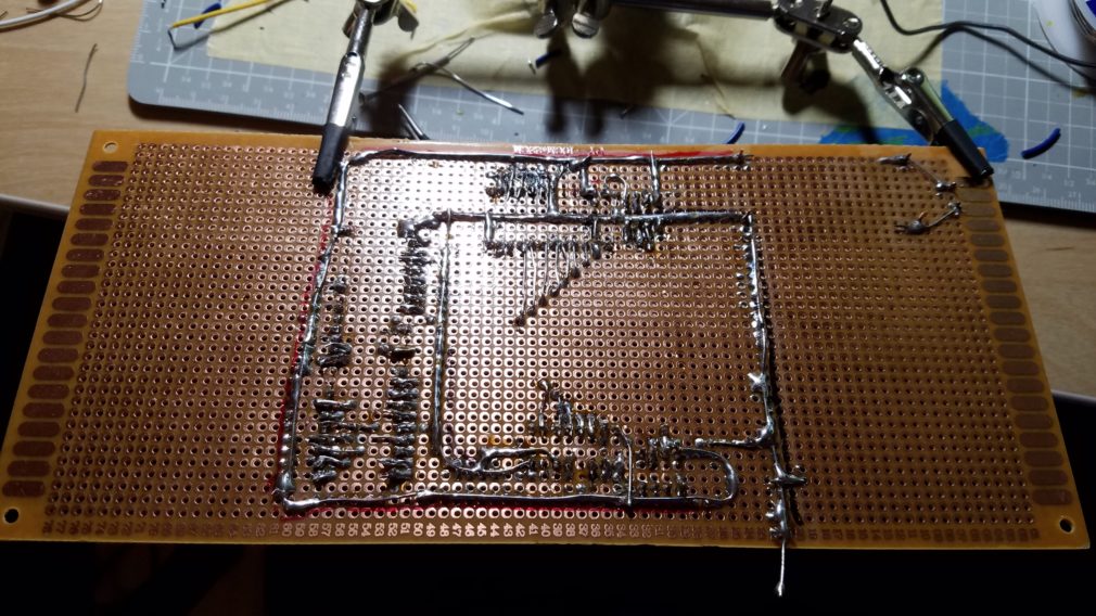
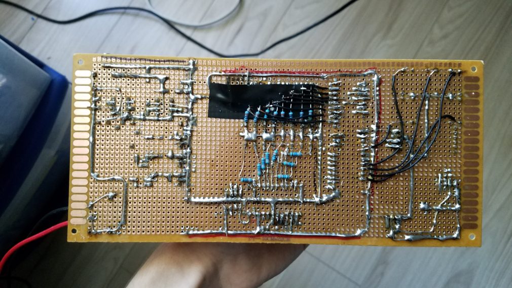
In the end, it worked out... but man, that was a ton of soldering. It took me about three days to solder everything together. Surprisingly, the part that I thought was going to take the least amount of time was layout planning - negative, that took forever too. Reason being is that I had to be careful how I laid out my components to ensure not only optimal "one-layer" wiring, but the easiest routing for my data bus lines and to make sure that I didn't back myself into a corner and run out of room for peripheral components! After a long-while of thinking and rearranging parts, I settled on a rough layout and just improvised it from there. It seemed to work out in the end, but there are a couple messy areas that unfortunately needed to happen in order to complete the circuit. Namely, the data-line LEDS. While these LED's are not important to the functionality of the system, I think they really do add a lot to the experience since you actually get to see the data flowing into each of the sound chips. Only problem is that these LEDs require bulky series resistors. I could have used resistor arrays, but I didn't have any on hand. I decided to use normal axial resistors, and while the final result looks pretty messy in my opinion, it seems to work just fine.

  • Roughly laying out the components

New Features

I've added a couple new big features to this project. First and foremost, Bluetooth support. As mentioned in my video above, controlling this project via USB is all well-and-good, but it introduces a ton of noise into the system. When connected via USB, the overly-sensitive DAC of the YM2612 picks up all sorts of electrical noise from spinning hard drives, fans, and even some interference from my mouse when ever I moved it around! To remedy this, control had to be performed wirelessly. The simplest way to do so would be to use a serial Bluetooth module, more specifically, the HC-06 module. This little extra daughter board provides a serial connection via Bluetooth to any device you want. You can connect to your HC-06 just like any other serial connection and control your project remotely via serial commands. On my main desktop, I am using a cheap Bluetooth dongle to connect to my project. If I were to open up the serial monitor, I would see two new COM ports. One port is for the actual dongle itself (we don't want that), while the other COM port is the virtual serial connection. Pick the correct COM port and it's just like having a wireless USB connection!

Speaking of noise... The I²C connected OLED display was by far the biggest source of noise in the entire project. Since this display refreshes frequently, it causes a very loud and annoying buzzing noise that really drowns out a lot of detail in the music. Originally, this OLED display was powered by the Teensy's on-board 3.3V regulator. I fruitlessly attempted to add some capacitors to this power connection in hopes that I could bring down the noise, but sadly, no dice. Eventually, I decided that I didn't want to strain the Teensy's regulator by powering too many peripherals, so I decided to give the OLED it's own dedicated LD1117 3.3V voltage-regulator. Surprisingly, this almost entirely eliminated the awful buzzing noise caused by the display. Hmm. Works for me!

Channel muting was added to the output lines of each chip. If you'd prefer to turn off the PSG for a particular song, you can just flip the mute-PSG switch. Don't want to hear the left or right channel? Flip those switches. It may seem like a pointless addition, but it's actually really handy if you'd like to single-out just the PSG or the YM2612 for a particular song.

Data bus LEDs were also added back-in. Even though they were kind of a pain to install, the result is well worth it. Seeing the raw 8-bit data flow in to each chip and hearing what sounds come of it really is super cool and adds a lot to the experience.

I've also included some dedicated on-board control buttons for forward, backwards, random song, loop mode, and shuffle mode. Previously, I used an external breakout board for these functions (or just used the serial connection), but now these buttons live happily in the top left corner of the main board.

Software-wise, I've made a few changes that significantly improved performance. First up, I've eliminated the need for near constant division when calculating delays and have replaced those routines with multiplication instead. Even though the Teensy features a floating point unit, multiplication is still significantly faster than division. Next, I discovered that command caching of all things was causing some performance issues. Previously, there used to be a 32 byte command buffer - the problem was that reading 32 bytes takes 32 times longer than reading just 1 byte. This means that the SD card read-speed is fast enough that I can read directly off of it without worrying about a command buffer taking extra time to read 32 bytes at once. I've still kept the buffer code, but have reduced the buffer size to 1.

A new watchdog timer reset system has been added. Sometimes, malformed VGM files (or files that aren't true VGMS!) lock-up my system forcing the user to power cycle. The new watch dog timer is activated when ever a new song needs to be loaded. If the song fails to load within 5 seconds, the system will automatically reset itself.

Lastly, I've been playing around over these last few months with my new CR-10 3D printer. I designed a case in Fusion360 and printed it out for this project. The print too ages (21 hours!), but the result was actually pretty good. Sadly, a little bit of warping on the front section occurred and messed up my interior dimensions a little bit. Instead of reprinting the whole thing, I took a pair of wire snips and trimmed down a few millimeters of the main board. I was nervous that I would crack the board and all of my hard work would be ruined, but it all went smoothly. I'm still finding little chunks of perfboard all over my room though...

How do you record your audio?

A common question I receive is how I record good-sounding audio off of my music player. Simple: I use my computers "Line-in" jack with audacity. Line-in is the light blue jack found on the back audio panel of most modern computers. Some PC's will combine the microphone jack and line-in jack (half pink, half blue), but just realize that line-in and microphone jacks are totally different!

My line-in level converter

Since the output is amplified, the signal is too "hot" for the line-in jack right off the bat. A simple solution would be to use a voltage divider to kick the audio down a few volts (without any degradation to quality!). To find which resistors to use, I simply grabbed two 10k potentiometers and winded them down until audacity shows readings that are loud, but not off the chart. I then measured both ends of the potentiometer with my multimeter to check impedance - turns out a voltage divider with a 1.2k+8.2k setup works perfectly! I soldered up a quick dual-voltage divider with audio jacks on each side and bingo! Works like a charm.

In audacity, I simply chose to record my line-in and it's as simple as that! 

Now this little level converter is really only designed for my music player in mind, so please be careful and don't blow up your PC's sound card. I take no responsibility for any broken equipment :)

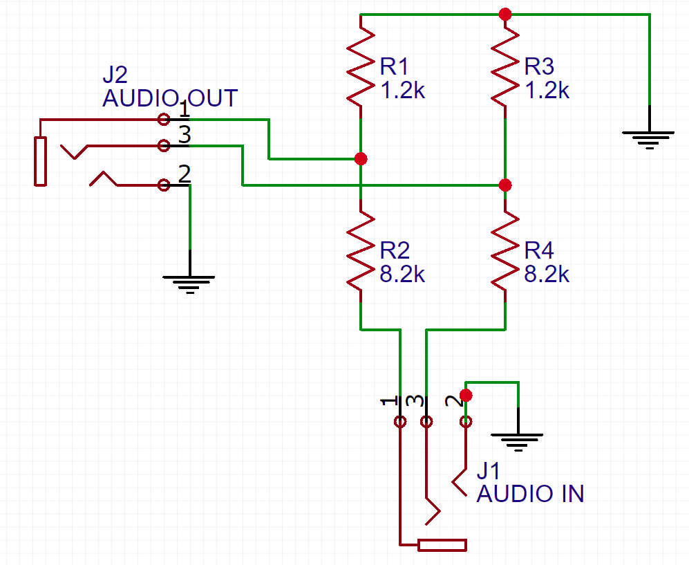
Schematic for the line-in divider

Where Do We Go From Here?

Q: Will I make a PCB version of this project?

A: Maybe. Probably not. Why? Making a PCB for this project would be an expensive endeavor. It would likely be a quad layer (or more) board and it would be pretty big. I would guess it would take around $90 to $150 to create a custom PCB for it. For now, the project sounds and performs great, so personally, I don't think I'll make a board for this circuit. I may, however, create a PCB for my latest project, an MSX video game music player!

For now, I think I'm going to put this project to bed and say that it is "done." I'd like to explore some other sound chips and maybe get into creating my own Z80-based microcomputer! We'll see where the next projects take us. I hope you enjoyed this series on the YM2612 and SN76489! New projects coming soon!

PDF