March 11, 2018
YM2151 Arcade Classic + Adlib Mini
Custom PCB’s for my latest and greatest hardware Video Game Music players


I have two new entries in my series on creating dedicated video game music players using genuine sound synthesizer chips. First, The Adlib Mini, which features the YM3812 (OPL2), a popular Yamaha synthesizer found inside many home computers during the mid to late 90’s – most notably included on SoundBlaster and Adlib sound cards of the era. Next, a much larger board based on the YM2151(OPM). I’ve named this project the “YM2151 Arcade Classic,” as the YM2151 was an incredibly ubiquitous FM synthesis sound chip found in high-end arcade cabinets in the mid 80’s to late 90’s. The YM2151 also found itself in a few high-end home computers of the era, most notably the Motorola 68000.
This time, I explore the processes involved with developing and manufacturing printed circuit boards for my projects as well as explore a new, cheaper alternative to the Teensy 3.5 that I normally use for projects like this.
Breadboard Prototypes
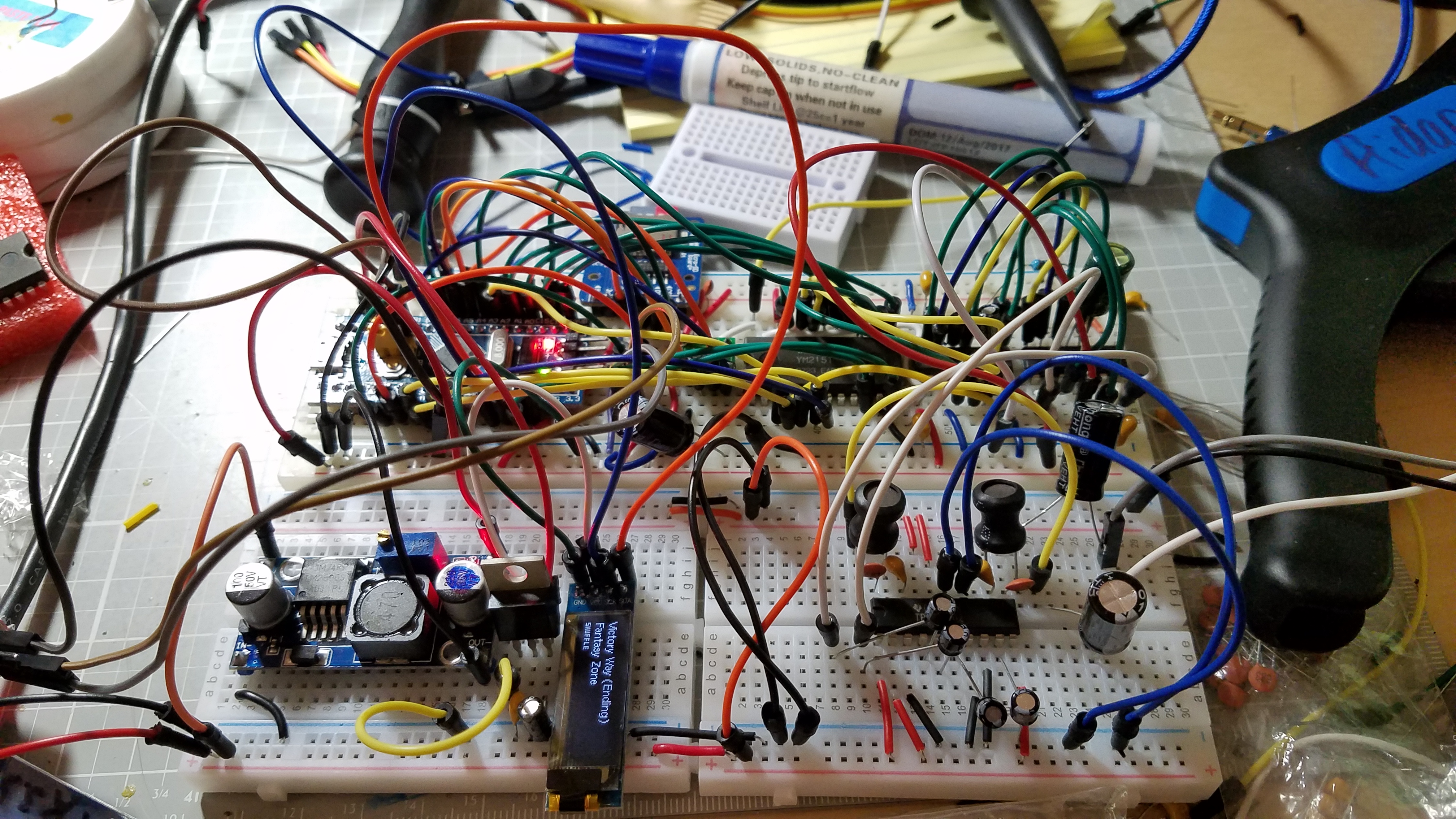
Here’s what the YM2151 Arcade Classic looked like on a breadboard
All of my video game music players begin their lives on breadboards. Breadboards are cheap, easy to work with for rapid iterations, and best of all, most of these older chips are still in DIP packages which makes working with a breadboard super simple! Some downsides to working on breadboards, however, is the often finicky connections which can make troubleshooting problems agonizing. Breadboards also have a tendency to have a bunch of stray capacitance and are very susceptible to electrical interference. These drawbacks and more often wreak havoc on the analogue side of things, namely, the amplification circuitry. So while I’m always proud of my little breadboard accomplishments, I’ve always wanted to graduate to the real deal with printed circuit boards. Fortunately for me, we’re now living in an era where anybody can affordably produce their own genuine printed circuit boards by themselves. Free software like KiCAD exist as “one-stop-shops” for electrical engineers to develop schematics, printed circuit boards, and component footprints. There is quite a bit of nuance involved, though, so be prepared to struggle with KiCAD for a few hours before getting the results you want. Just like everything else in life, it just takes practice.
Creating Printed Circuit Boards
The scope of this post is not to be a tutorial on creating PCBs, but I’d just like to give you a preview of what’s involved with the creation process. Firstly, as mentioned above, I start my circuits out on a breadboard. This serves as a rapid prototyping stage where I can plan out my circuit and identify components. As you can probably tell, I’m really not too concerned with looks at this stage, sorry pretty breadboard people. Once I’m happy with the breadboard circuit, I must then create a schematic in KiCAD.
One of the biggest challenges with working with KiCAD is getting over their horrendous library management system. KiCAD would be the ‘perfect’ EDA solution for me if it wasn’t for the library system in my humble opinion. Libraries and modules, for those who don’t know, are essentially electronic part files that contain their schematic symbols, board footprints, 3D models, etc. Ranting aside, just know that if you decide to work with KiCAD, be prepared to be frustrated with importing and exporting parts and symbols.
Once I’ve located all of the part symbols that I require for a project, I begin creating the schematics. I use the breadboard prototype as a guide for my schematics and carefully document where each and every component is connected. After I’m done drawing the schematic, it’s time to double, triple, quadruple… wait a bit… then quintuple check to make sure that everything in the schematic is represented properly and that each component is connected to where they need to be connected. Even after you’re sure that your schematic contains no errors, it’s very likely that somewhere down the line you’ll spot one little issue that you’ll need to go back and correct. The less of these tiny issues there are, the more time you will save in the long run.

The schematic for the YM2151 Arcade Classic
Next, it’s time to link schematic symbols to their component footprints in KiCAD’s cvPCB. This is yet another laborious and long process as it is pivotal that you select footprints and dimensions that accurately represent your parts. One-by-one, you must go down each and every component and link them up with their respective footprint. A footprint is simply a representation of an electrical component a printed circuit board. Footprints contain the dimension information of a component as well as their pin/pad positions and data pertaining to the silkscreen. Footprint selection is yet another time where checking several times over will save you lots of hassle in the future. Also, be prepared to yet again wrestle with KiCAD’s library system. Much like schematic symbols, you can find lots of component footprints online and import them for use in your own project. In fact, Digikey will often give you a few free footprints on select components on their site. You can of course, create your own footprints using KiCAD, but prepare to bust out the calipers and take some measurements if your part is not of a standard size. I had to create a custom footprint and schematic symbol for a 128×32 I2C OLED display which you can download here if you need it.
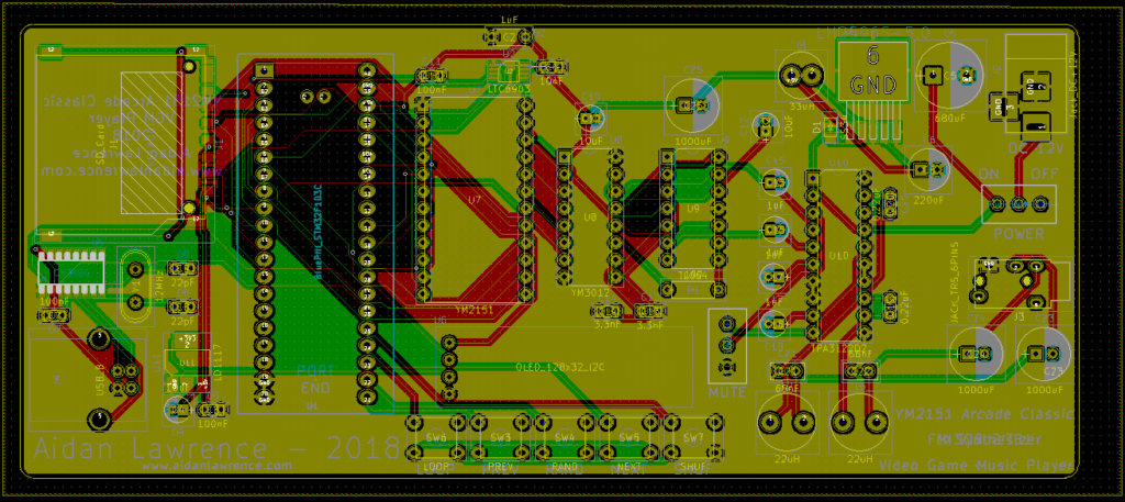
The printed circuit board for the YM2151 Arcade Classic in KiCAD
Finally, you’re ready to begin creating your printed circuit board. After using KiCAD’s netlist generator, open up PCBNew and import said netlist. You’ll be presented with a condensed blob of all your components. Protip, follow this guide to space your components out automatically so that they’re easier to work with. After hours of placing components, routing traces, creating silkscreen assets, and pouring copper, you’ll eventually have a board made. Make sure to use the automatic design rule checker and see if you have any unconnected traces. Once you’re satisfied with your board, I recommend waiting for a couple hours and THEN coming back to it to see if you have any mistakes. Sadly, on my original iteration of the YM2151 board, I wrongly assumed that micro SD cards have identical pinouts to full-sized SD cards. They in fact, are slightly different. Damn. Nothing a little bodge wire can’t fix, but they’re definitely blemishes on something you’ve worked so hard on. Nothing to really worry about though, even tech giants often have lots of bodge wires running throughout their boards!
Once you’re completely satisfied with your board, it’s time to export the Gerber files and send them off to the board house of your choice. Some good ones that I have found are JLCPCB.com and OSHPark.com
For both The Adlib Mini and the YM2151 Arcade Classic, I went with JLCPCB. They’re faster, offer more colors, significantly less expensive than OSHPark, and in my opinion, have superior quality boards. Be warned though, JLCPCB is a Chinese manufacturer. While I have no reason to suspect that they will rip off your board designs, it absolutely something to consider if you have proprietary designs that you would like to keep secret. In that case, it’s better to go with a domestic board house. For totally open project prototypes like this though, JLCPCB all the way! Make sure to check with your specific board house how they would like to receive your CAD files as most of them are different. OSHPark will conveniently just take your raw KiCAD files automatically while JLCPCB requires a bit of setup to export Gerber files. Either way, send out your files and prepare to wait a little while. Soon enough, you’ll have some lovely raw boards! Warm up your soldering iron and go nuts! My schematic and PCB files are all included in the open-source repositories for both the Adlib Mini and the YM2151 Arcade Classic.
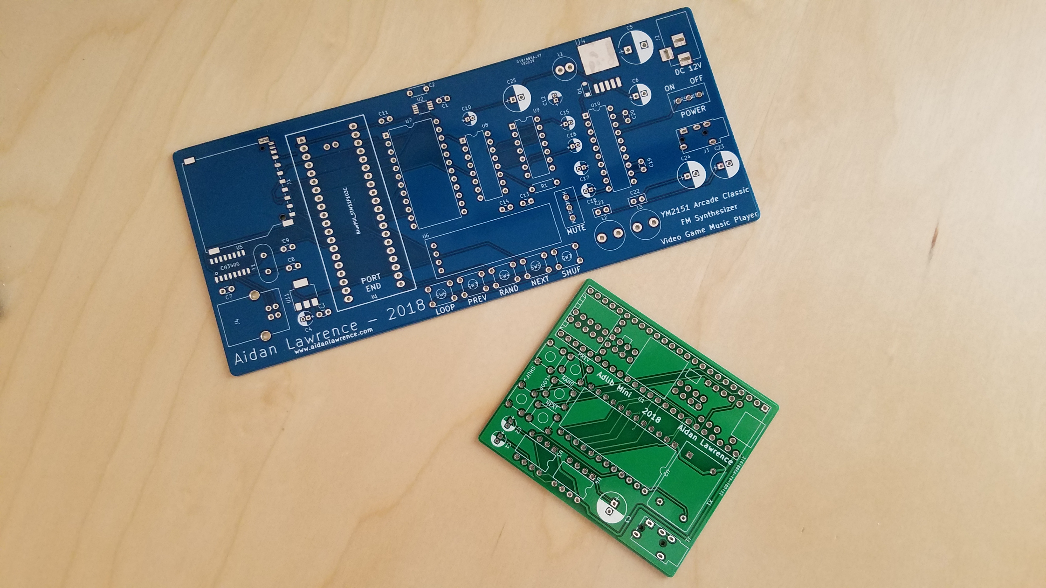
Finished printed circuit boards!
A New Architecture
For the Adlib Mini, I stuck with the familiar Teensy 3.5. Teeny boards are absolute beasts – so much so that the majority of that power and I/O goes to waste with these simpler FM chips. On top of that, Teensy 3.5’s are EXPENSIVE, nearly $40 a pop. I needed an IC that was still speedy, 32-bit, and had enough RAM to do the job. Enter the STM32 “Blue Pill” boards. These boards feature an Arduino-compatible STM32F103C8 microcontroller. These are plenty-capable of driving the lower-end sound chips that I’ve been using recently and best of all, they’re about $2 each. WOW. Downsides? No built-in SD card support, no built-in USB-to-Serial chip, and significantly less RAM. The clock speed is only a fraction of the Teensy’s too, but the STM32 still runs at an admirable 72 MHz. With a bit of patience and an external USB-to-Serial breakout board, I was programming this new board with ease! It’s a bit tougher to work with than the Teensy, but I mean… you just can’t beat that price. You can find a great tutorial on the STM32 boards here.
Lack of USB-to-Serial and native SD card support was a little bit of a challenge for the final board, though. Thankfully though, SD cards are just standard 3.3v SPI devices and the cheap-but-reliable CH340G UART chips are easy to use, though they’re a bit tricky to find outside of eBay.
Amplification and Power
The YM2151 Arcade Classic requires a multitude of voltages on board. 12V, 5V, and 3.3V. This means that I needed to create a few power regulation circuits so that my board could have all the voltage levels it needed while only having one power jack. 12V comes in from the power jack and is used for the amplification circuit. This 12V is then bucked down to 5V by an LM2956 and is sent to power all of the logic-level ICs. This 5V supply then feeds into a 3.3V LD1117 low-dropout regulator that powers the SD card and OLED display. The STM32 has it’s own on-board 3.3V regulator used exclusively for the microcontroller.
I’ve made a new amplification circuit for the YM2151 Arcade Classic. First, the YM3012, the external DAC for the YM2151, is connected to a TL074 quad op-amp. This op-amp acts as a voltage follower and buffer. The stereo output of the TL074 is then sent to a TPA3122D2, a stereo class-D amplifier. The TPA3122D2 is quickly becoming my favorite power amplifier thanks to it’s easy-to-use DIP package, power output, clarity, and the fact that it’s stereo! You can find an excellent tutorial on the TPA3122D2 here, though I’ve used different component values for my circuit.
PCBs Forever
Now that I’ve got a few PCBs under my belt, I will be creating them for nearly everything! PCBs do take quite a bit of time and effort to produce, but honestly, the results are totally worth it. Not only do the final boards look so pro, they also significantly improve the performance of your circuits compared to breadboard prototypes. We’re living in the ‘maker’ age where affordably producing your own professional products is only a few clicks away. Definitely worth the effort.
This is beautiful. I am Opl3, Opl2 fan. I have Opl2 Adlib clone also SB16 with OPL3. Want buy 2xYM2151board and 2xMiniAdlib from You.
Hi,
Just finished this build, just need to upload the firmware. Quick question, what amp and polarity is the power supply.
Regards
For the Arcade Classic:
Center-positive, 12V, and at least 300mA.
Thanks for the info, looking forward to using it.