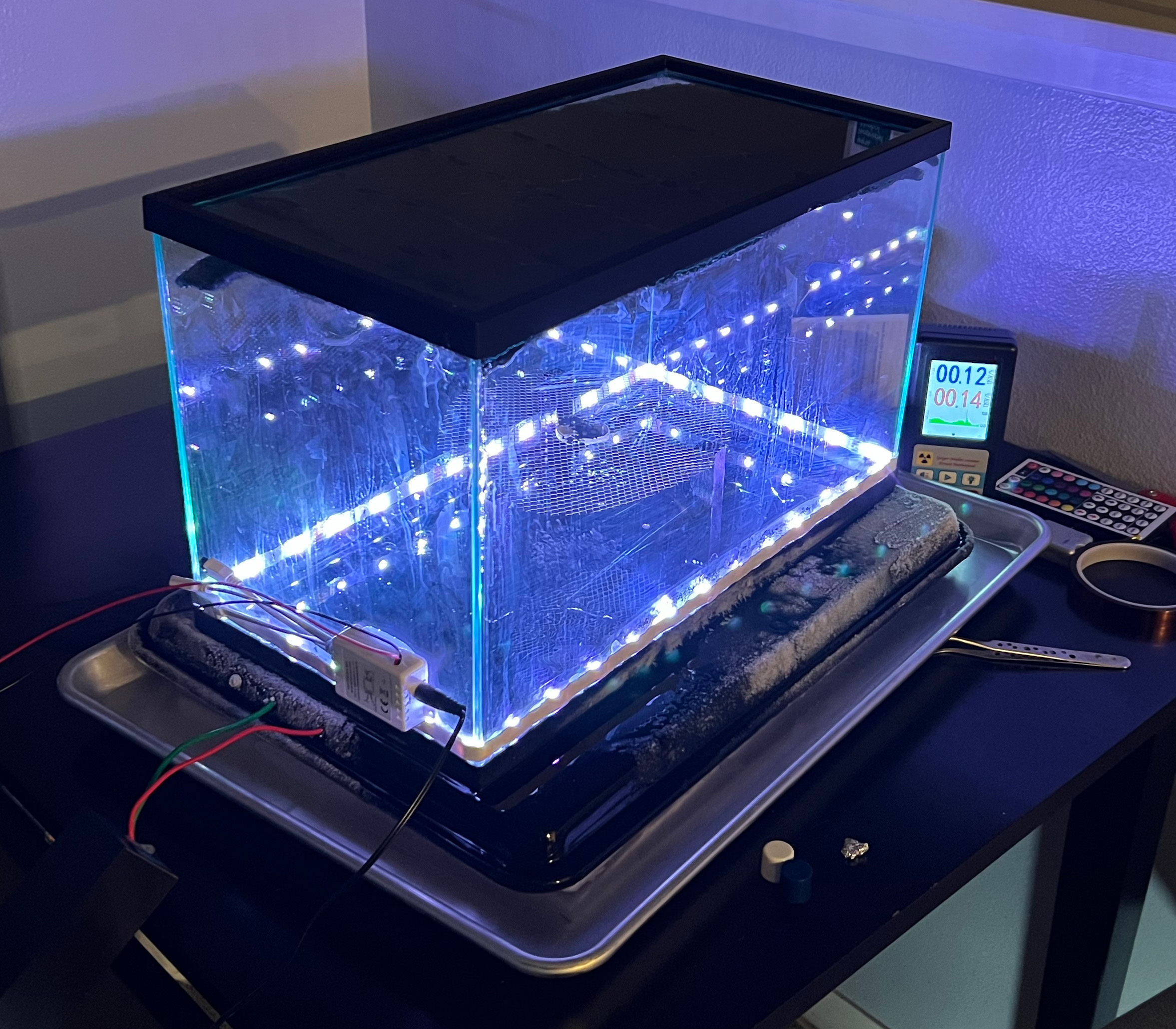
Building a Cloud Chamber to Visualize Ionizing Radiation

March 10, 2024

Literally and figuratively speaking, this project was very cool. You can view it working here.

Over a spare weekend, I built myself a Cloud Chamber – a device that allows you to visualize ionizing radiation from radioactive sources and from the natural environment around you. With a cloud chamber, you can witness trails of condensed isopropyl alcohol vapor the follow the paths of ionizing radiation particles. You can witness alpha particles, beta particles, the residual products of gamma rays and even some remnants of cosmic rays if you’re lucky!
Since the radiation itself is invisible, this serves as an amazing way to viscerally experiment with simple particle physics.

Before I continue, I must warn that Cloud Chambers are quite a bit more hazardous than what a lot of online sources will have you believe. Dry ice, cryogenic alcohol which is also flammable, high-voltages and naturally, radioactive exposure risks if you happen to have sample sources to test. My design was pretty improvised – while it did work really well, there was a lot of design changes I would have made after the fact if I were to ever do this again. I wouldn’t recommend you recreate my exact project, but I figured I’d share what I had made anyways because this was awesome. With all this being said, if you attempt this experiment yourself, please be aware of all the risks and take all necessary precautions to keep yourself safe. This is quite dangerous and if you don’t understand or aren’t comfortable with these risks, don’t try this at home! You’ve been warned!

Inspiration

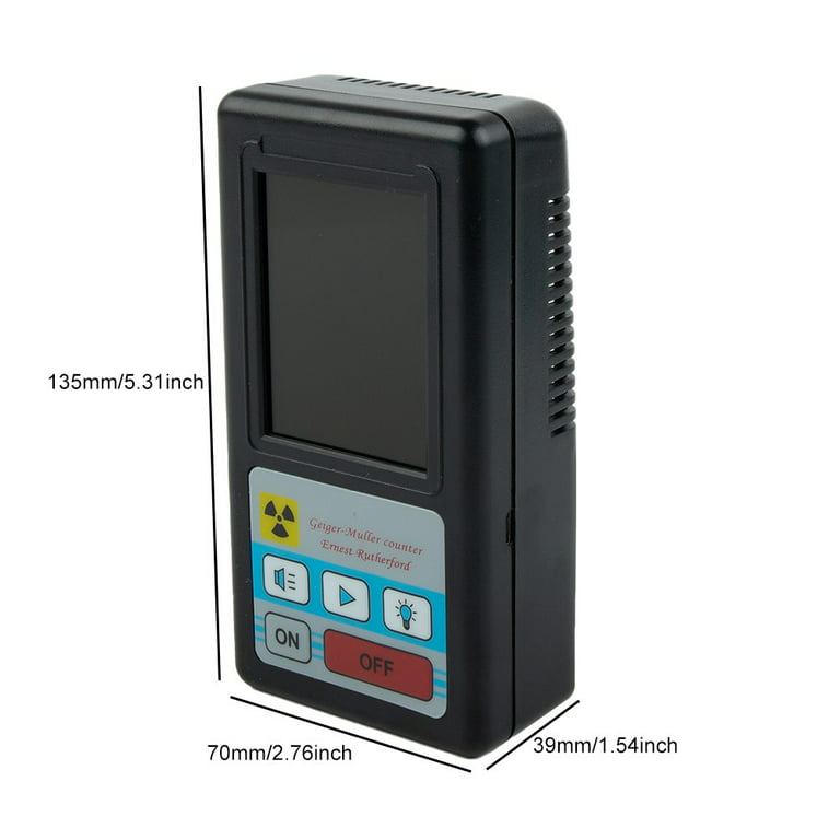
I’ve always been pretty interested in simple nuclear physics for a while now. Unfortunately, it’s not exactly a cheap hobby. Even basic Geiger counter kits were historically pretty expensive. Well, at least they used to be! Nowadays, there’s a treasure trove of cheap Geiger-Muller tube based counters out there that you can grab from Amazon and Aliexpress. Around $30 can get you a BR-6 – a dirt cheap unit with a genuine tube inside of it. Is it a bit crap and probably gives wildly inaccurate dosage readings? Yeah. Does it actually have the ability to detect ionizing radiation? Also yes!

BR-6 Geiger Counter Handheld Nuclear Radiation Detector Dosimeter β γ X-Ray - Walmart.com

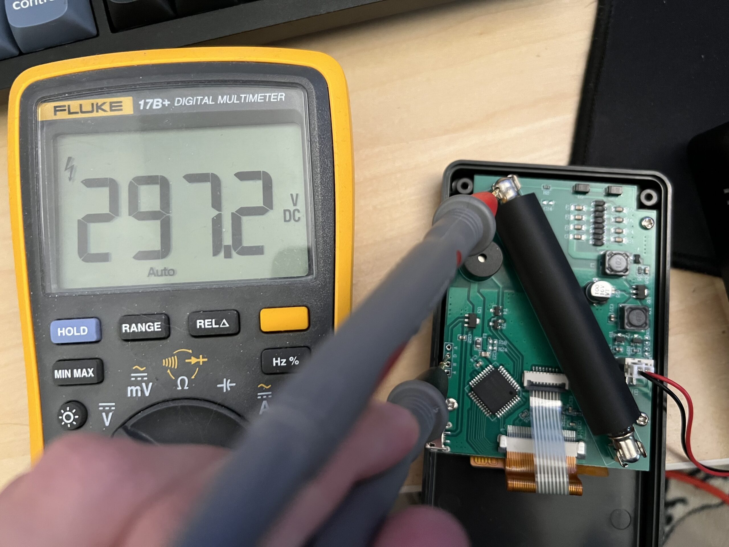
Four screws later, and you’ll find a simple circuit board with a few power circuits, a microcontroller, a piezo beeper and a genuine Geiger-Muller tube in black heatshrink (I presume to minimize exposure to UV? Dunno if that’ll actually do anything, but neat).

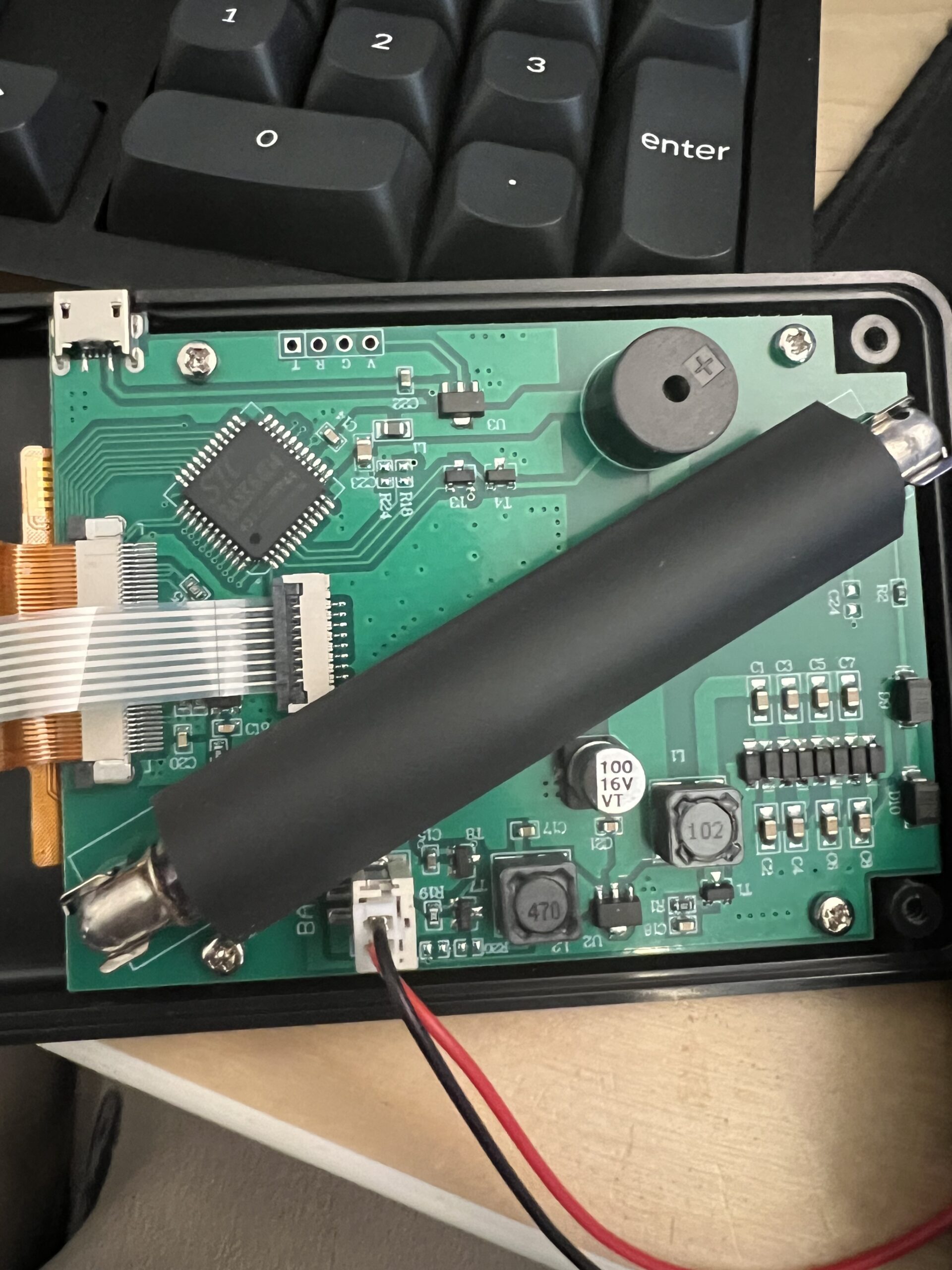
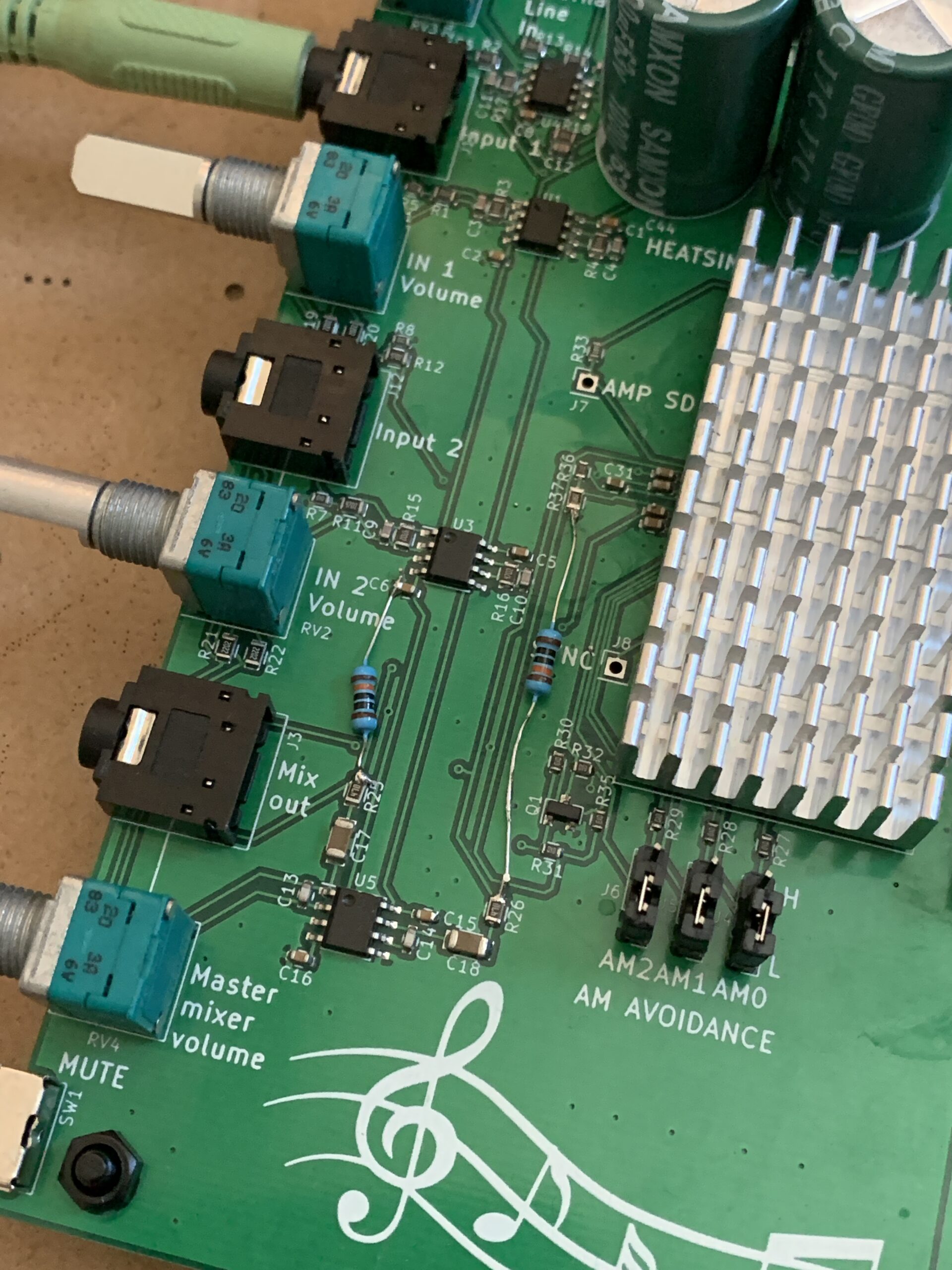
BR-6 PCB. Notice the large black Geiger-Muller tube in the center. The high-voltage boost circuitry runs along the bottom-right side and up through R2 to the tube on the far right.

If you do decide to open up this unit, please be careful! There are some pretty high voltages here to charge the tube. I measured around 300V! Not recommended.

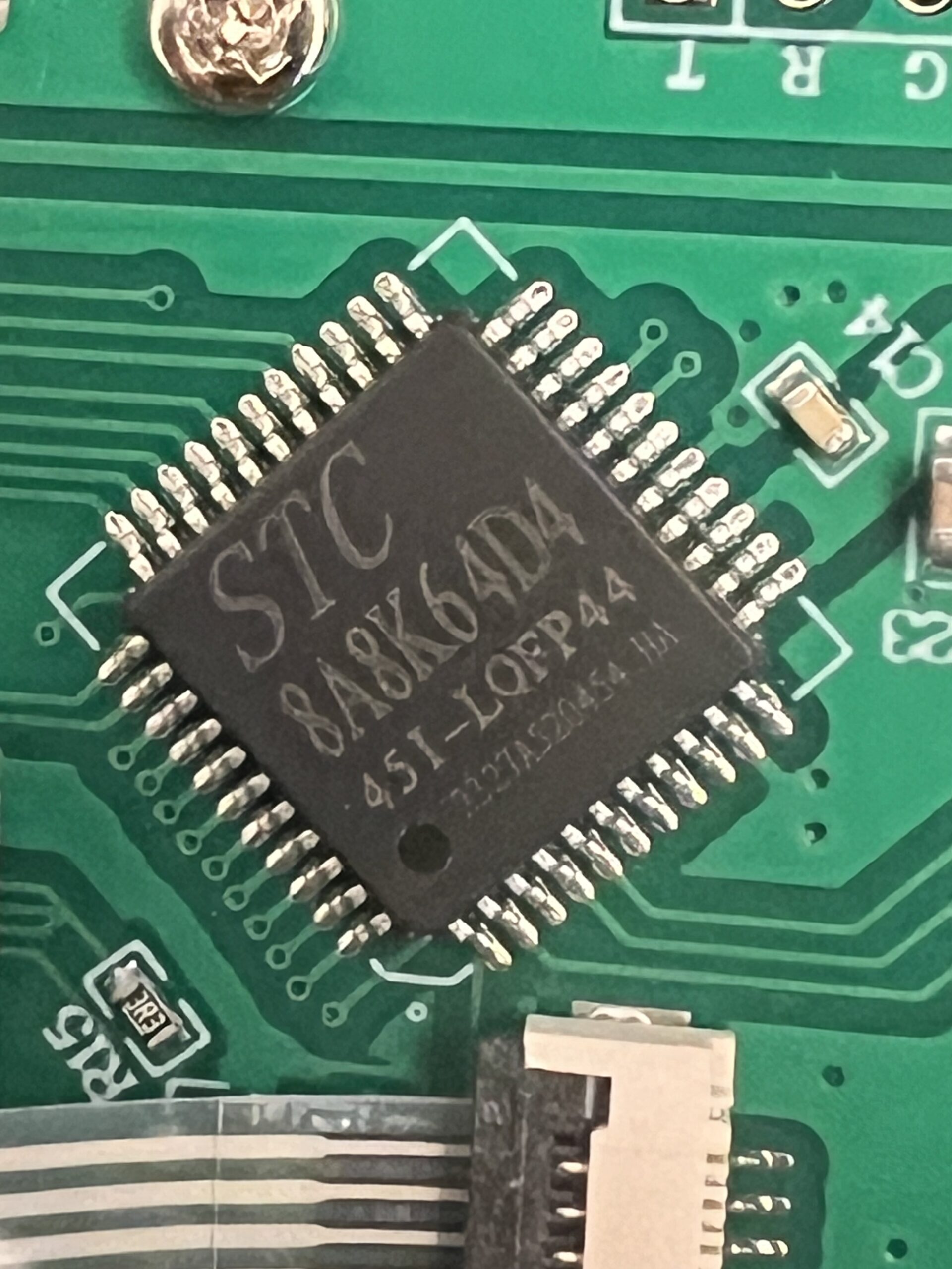
STC 8A8K64D4 microcontroller. Cheap 8051-based thing.

Spicy!

I digress…
Once you have a Geiger counter, you’ll probably want to measure something with it. Most houses actually have several small, but relatively strong sources of ionizing radiation: smoke detectors!

Not wanting to destroy my working smoke detectors, I bought one on Amazon and tore it down.

Again. I must warn you. The following is not safe and you are taking unnecessary risks if you decide to duplicate what I’ve done. Exposure to radioactive sources is dangerous, even if the source is small.

Most smoke detectors contain an ionization chamber that contains a minuscule amount of radioactive Americium 241 in the form of a tiny mixed metal foil pellet in a steel chassis. The Americium is actually Americium-Oxide sandwiched between (in my case) gold foil that helps prevent it from contaminating it’s surroundings should someone come poking at it :).
Photoelectric-style smoke detectors don’t contain a radioactive source. If you check the packaging or labeling on your smoke detector, there is a good chance that you’ll see a blurb about the radioactive source within so long as you’ve got an ionizing one.
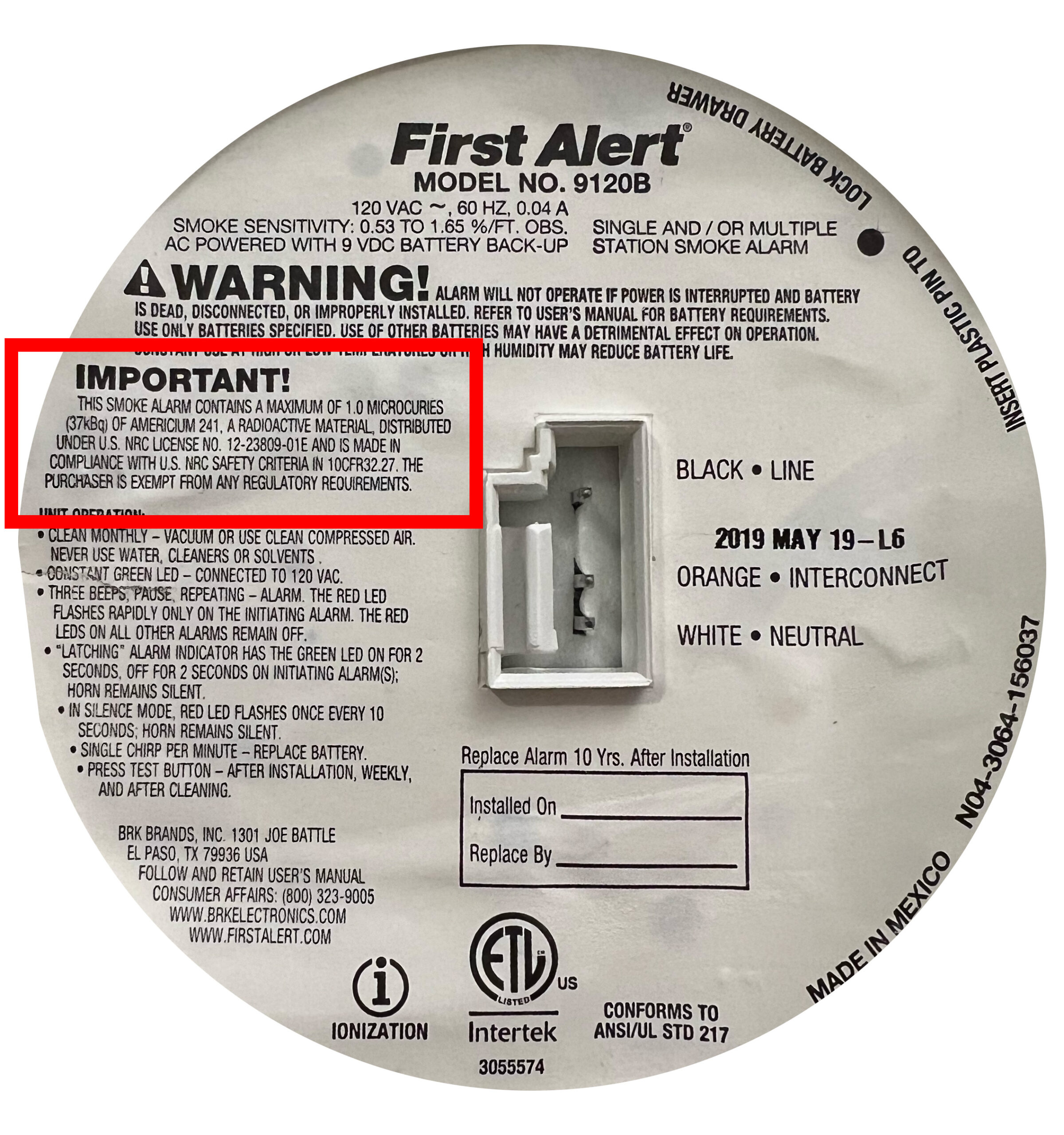
Am-241 is primarily an alpha particle emitter, which the BR-6 cannot detect. However, Americium and it’s decay products also occasionally produce gamma rays which the BR-6 can detect. While gamma rays tend to sail right through just about everything, the fairly intense alpha particles are easily stopped by paper, gloves, glass and skin. There is less than one micro-curie of radioactive material here, which is very tiny. That being said, even though the source is small and much of the radiation can be blocked by simply wearing gloves, limiting your exposure time and showing caution is still required. Remember, this is also a source of gamma radiation. A more nuanced explanation of how safe smoke detector sources are can be found here on the U.S. Nuclear Regulatory Commission’s website. TL;DR, me handling this source briefly is fine so long as I’m cautious. I’m under no illusion that what I’m doing is safe, but I’m not eating this thing or dremeling it.

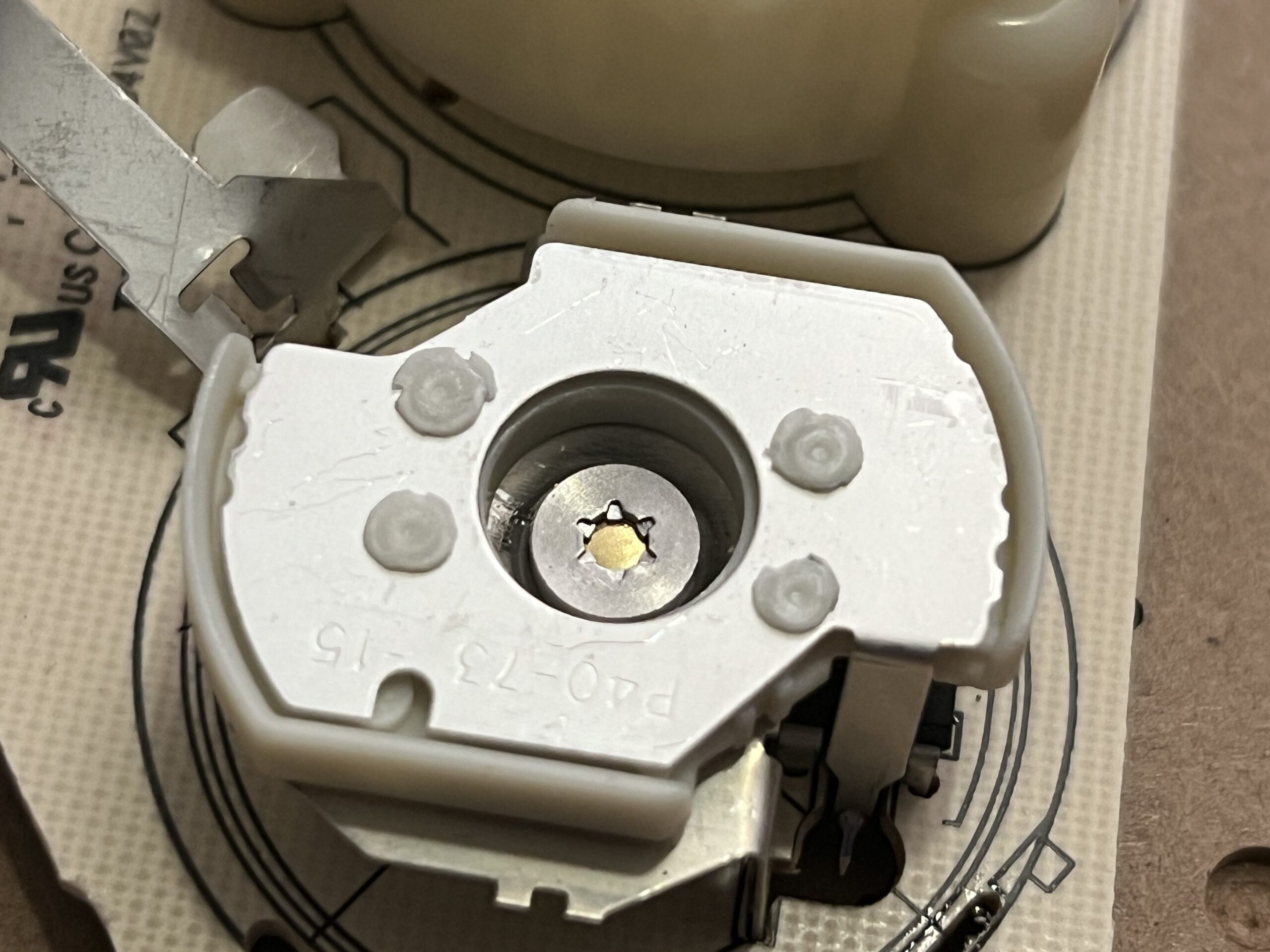
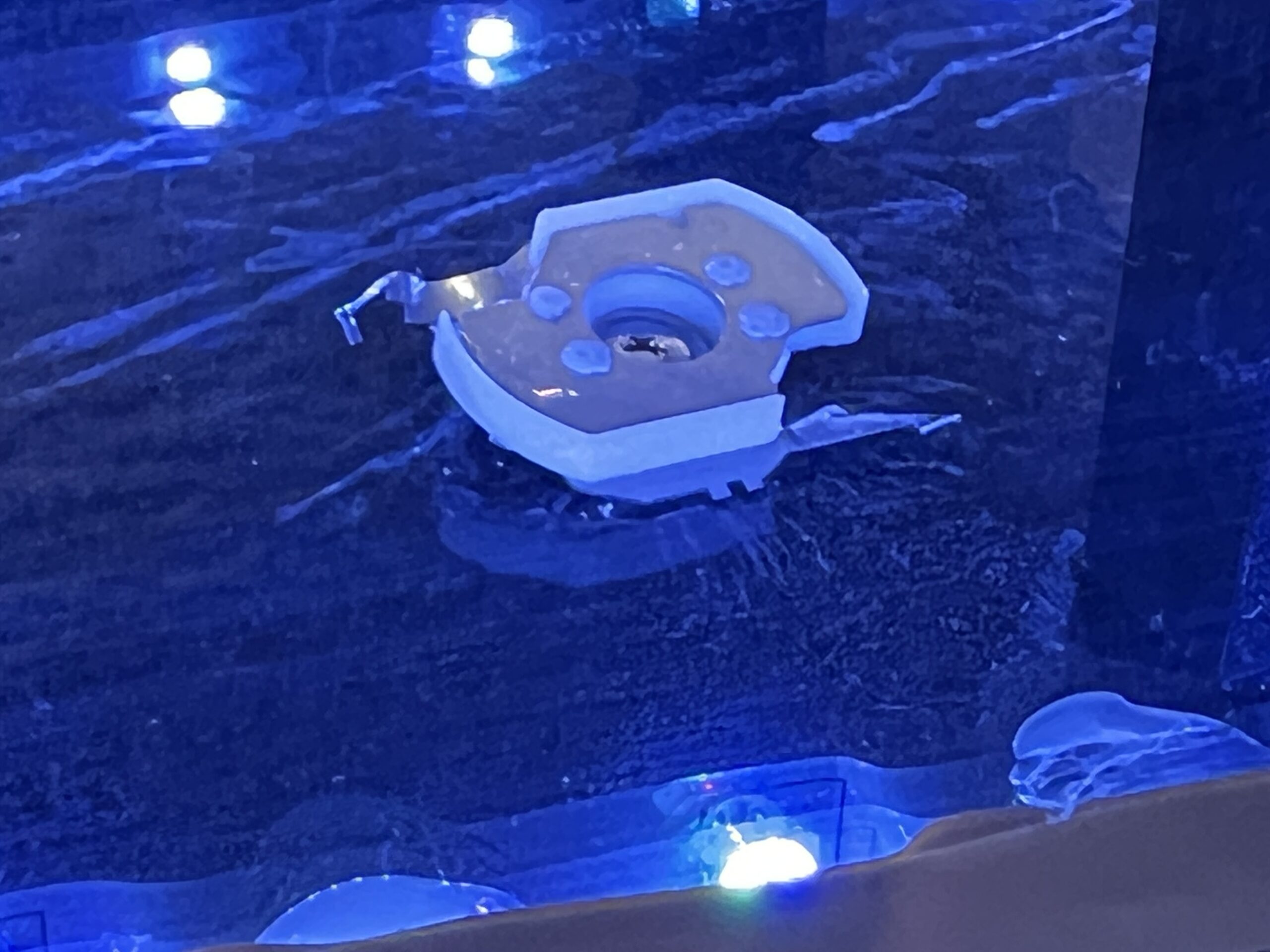
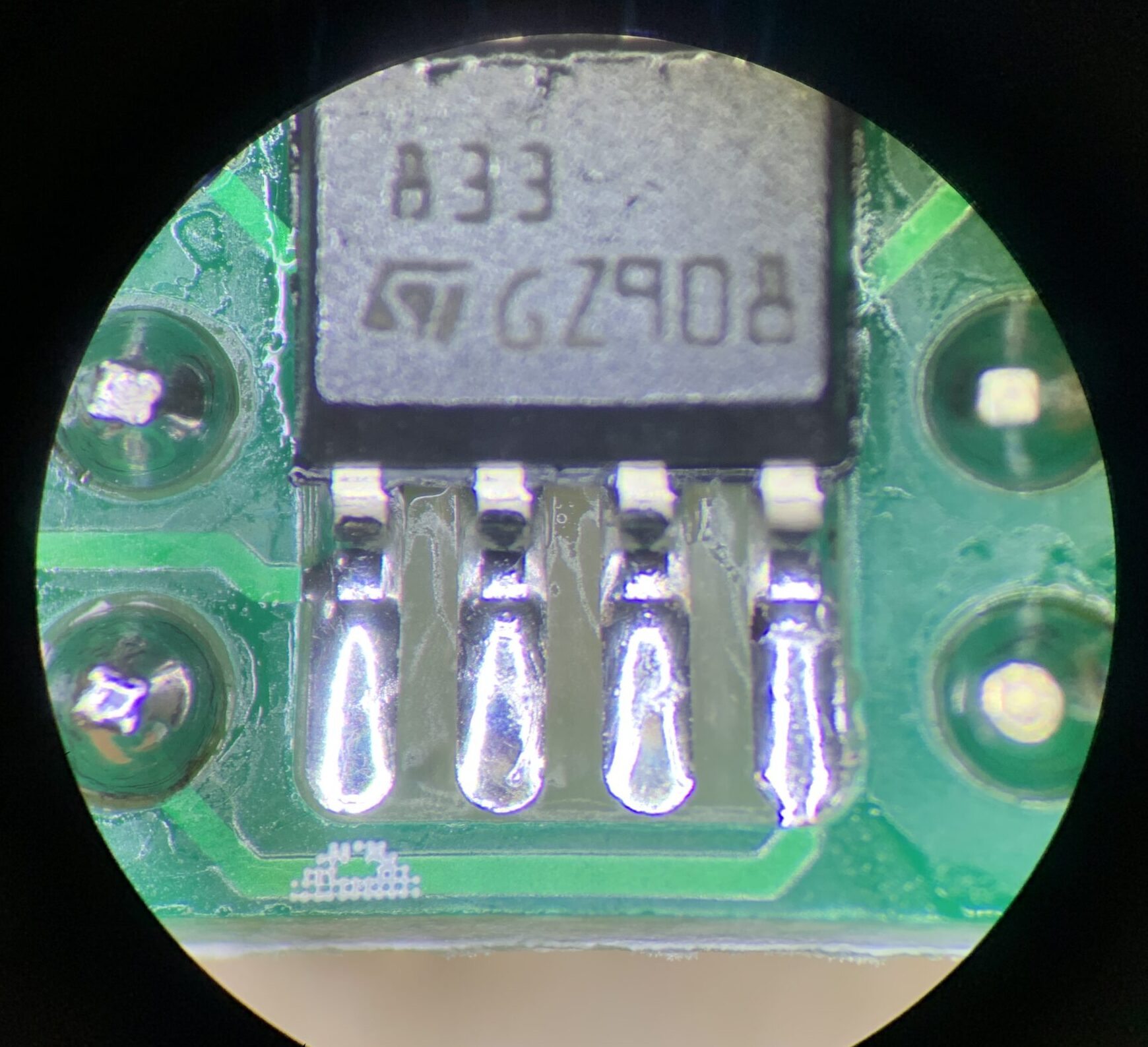
The ionization chamber opened. Notice the gold disk in the center. That is the tiny Americium 241 payload with a gold foil covering it.

Getting slightly closer with a macro shot.

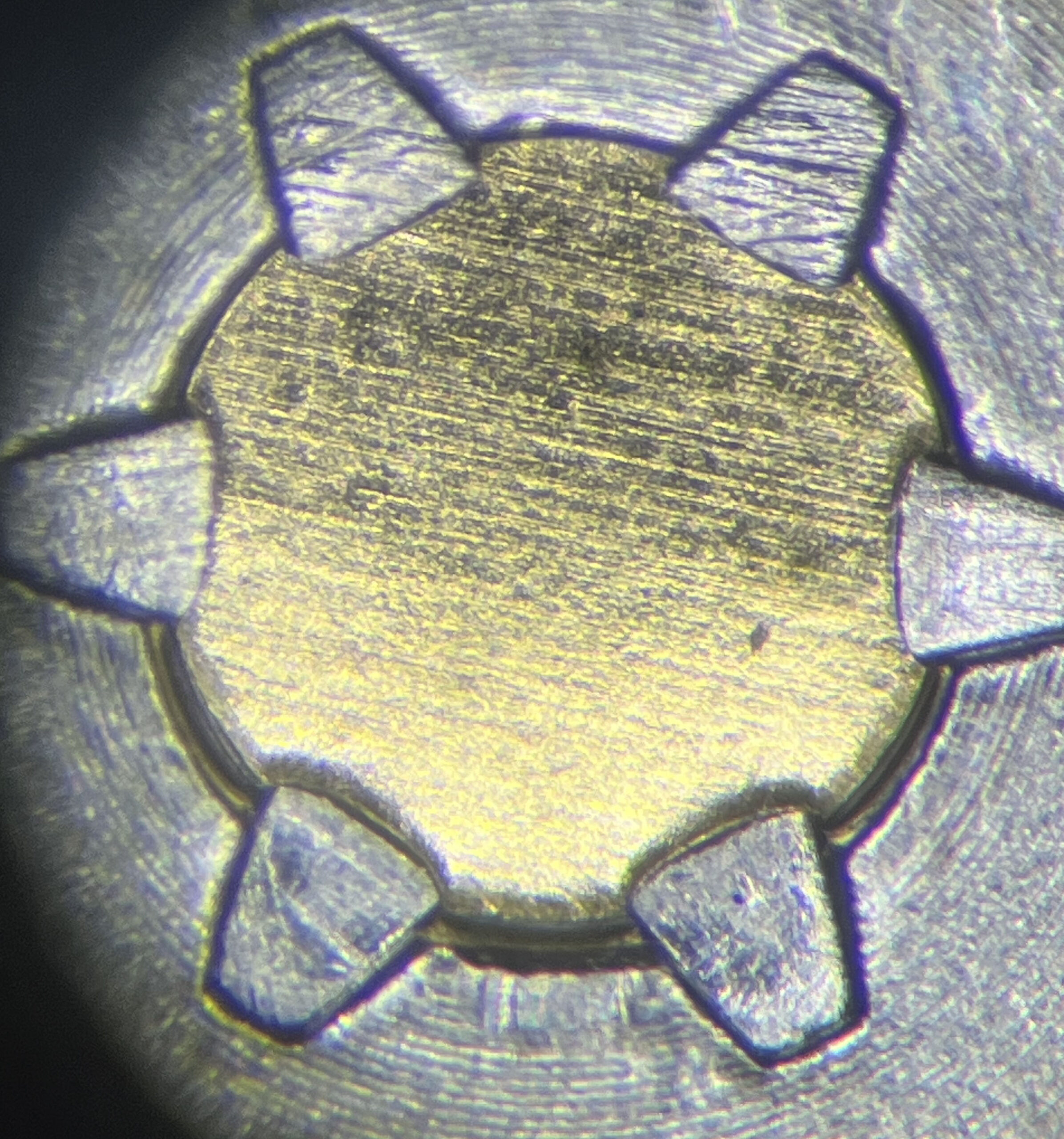
Here’s a view of the source through my microscope. The Americium Oxide is contained within a golden foil sandwich. Looks pretty spooky!

As you can see from the video above, this source certainly kicks off enough gamma radiation for the BR-6 to pick up. Again, I wouldn’t trust that dose reading at all, but it is neat to see it respond to something radioactive.


The BR-6 is also able to slightly pick up sources of beta radiation. Thoriated tungsten welding rods contain about 2% thorium by weight, making them radioactive as well. I picked up these rods after my cloud chamber experiment, but I just thought I’d mention them if you’re looking for easy test sources that emit beta particles.


COOL! Now what?

Watching the meter click a bit when I put it up against the Am source was pretty neat. That being said, this kind of detector isn’t really suitable for alpha radiation. Videos online from people that have devices capable of detecting alpha particles show their counters absolutely scream when they’re held up to smoke detector sources, so I kinda’ felt like I was missing out on the science.

There was an interesting and fairly affordable way I could actually see (visualize, I know) these alpha particles though. Build a cloud chamber!
…and so it shall be built. I took spontaneous trip to Walmart to gather an eccentric list of supplies. You know you’re doing something interesting when you get a comment from the clerk while checking out.

I didn’t really have a build plan for this thing. I just kinda’ surmised what I needed from memory under my assumptions on how this thing was supposed to work. Now that I’ve built the thing, I know what I’d do differently, but my original parts list comprised of…
2x thick metal cookie sheets. One smaller than the other so that they’d fit inside one another.
2x foam-core poster boards to act as an insulating building material that I could fit dry ice inside
1x can of flat black spray paint and a can of flat black primer
1x 5 gallon glass fish tank
1x 8 liter cooler for holding dry ice
1x cheap RGB-LED strip kit
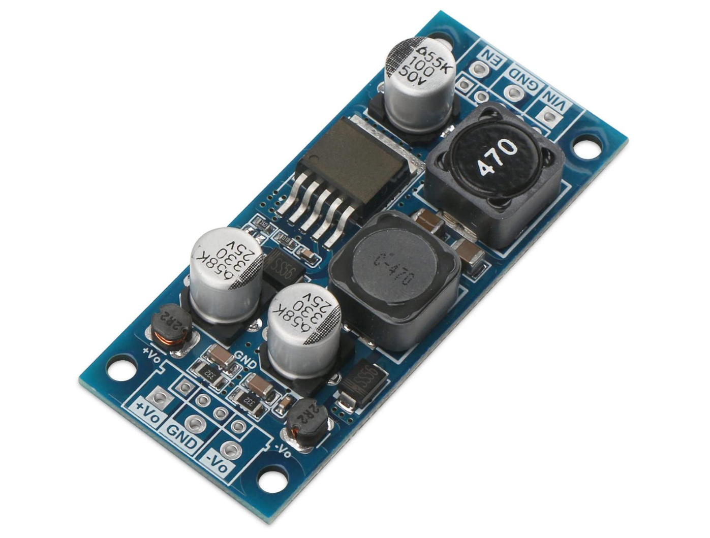
1x LM2596 buck-converter module
1x roll of foam weather stripping (mistake. This stuff sucks and I removed it in the end)
1x electric fly swatter for generating a high-voltage field within the chamber

..and like just a bunch of stuff I had lying around like wires and a ton of 99% isopropyl alcohol (wait, you don’t keep liters of that stuff on hand?). Everything else was 3D printed.

Theory of Operation

Alright, cloud chambers are actually pretty simple.
You have a chamber. You have a sponge or felt material soaked in isopropyl alcohol inside the chamber. You have lights around the bottom of the chamber to illuminate it. The metal floor of the chamber is painted black for good visibility and is super-chilled by dry ice. You generate a high-voltage field to make it work better (ok, maybe that last one is slightly more advanced).

Anyway, the chamber becomes fully saturated with alcohol vapor. If you could imagine the weather with “100% humidity,” where the air simply can’t hold any more water, the same thing is happening here. It’s just saturated with alcohol rather than water.
That alcohol vapor isn’t able to condense throughout the majority of the chamber since the ambient temperature is too high. That’s where the dry ice and the cold metal plate come into play. The extremely cold plate allows the alcohol to condense onto it, but that’s not exactly what we’re interested in. Directly above the cold plate is a zone of ultra-saturated, cooled alcohol vapor that’s just on the cusp of condensing, but it just can’t quite make it yet. When ionizing radiation, either from a dedicated source, or from naturally decaying radioactive nuclei around you, or even the remnants from cosmic rays from space rip through the chamber, it ionizes the air. Since alcohol is a polar molecule, it becomes attracted to the particles that have become charged from the radioactive particle zipping through. This attraction rapidly causes a condensation trail to appear which is visible to us. I’m simplifying slightly, but that’s pretty much the jist of it.
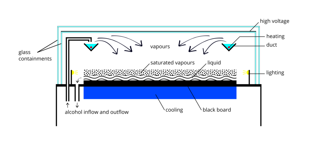
Credit: Nuledo

Time to Paint

I began by roughing up the smaller of my two cookie sheets with some brass wool (same stuff I use for cleaning my soldering iron tips).
This was just to help the primer stick better.

I didn’t use any special metal primer, just some Rust-Oleum flat black primer. I evenly sprayed down one coat, let it dry for about 40 minutes, then put down another coat. I let that dry for about an hour.
Once it was dry, I roughed it up slightly with some scotch-bright. Just a quick once-over seemed to suffice. There’s lots of painting advice online for doing this “right,” and it usually involves much more sanding and time, but to be honest, this worked just fine and gave a perfect result.
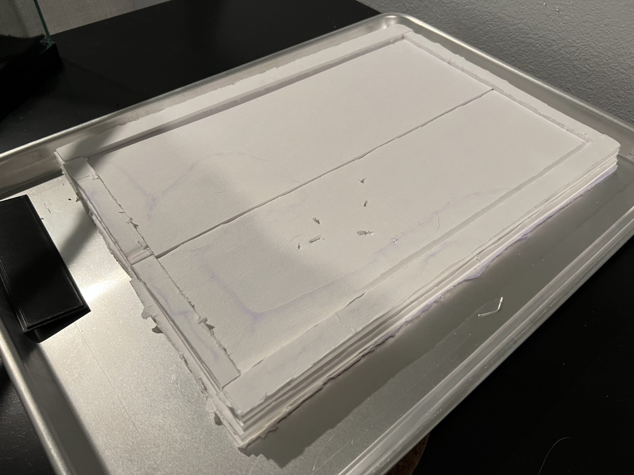
I sprayed it down with one good layer of flat black paint and let it dry overnight. The finish looked great! You really want a perfect black stage here.

(Forgive me, I wasn’t planning on documenting most of this process, so this image was made post-experiment. Should give you an idea of the paint job, even if it was a little scuffed-up after my first run)

Foam Insulation for Dry Ice

This step was pretty easy. Since I was going to have the black cookie sheet rest upside-down, I wanted an elevated platform that would insulate the dry ice, keep it confined and also push it up into the cookie sheet. I just used some foam science project poster board for this. I measured the interior of the top cookie sheet, then created a platform with 4 layers of foam sheet hot-glued together with some guides on the side to keep everything in place. Worked surprisingly well! Styrofoam would have been my preferred choice here, but those boards were certainly easier to build with and way less messy.

Again, this shot was post-experiment, so the foam is a bit scuffed-up. (we played with the dry ice a little after, hence the dents :P)

Alcohol Reservoirs

Here’s an example where the simplest solution ended up being the better one. I had originally designed some alcohol reservoirs in Fusion 360 and had printed them out. These reservoirs were stuffed with gauze padding with a string of resistors running through them to provide enough warmth to heat the alcohol and evaporate it better. These would have probably worked, but honestly, it just seemed like a pain to wire them all up. Remember, the chamber has to be pretty air-tight and everything is exposed to some pretty nasty conditions with solvents, cryogenics, etc. Also, I didn’t want to accidentally miscalculate something and cause an alcohol fire :)

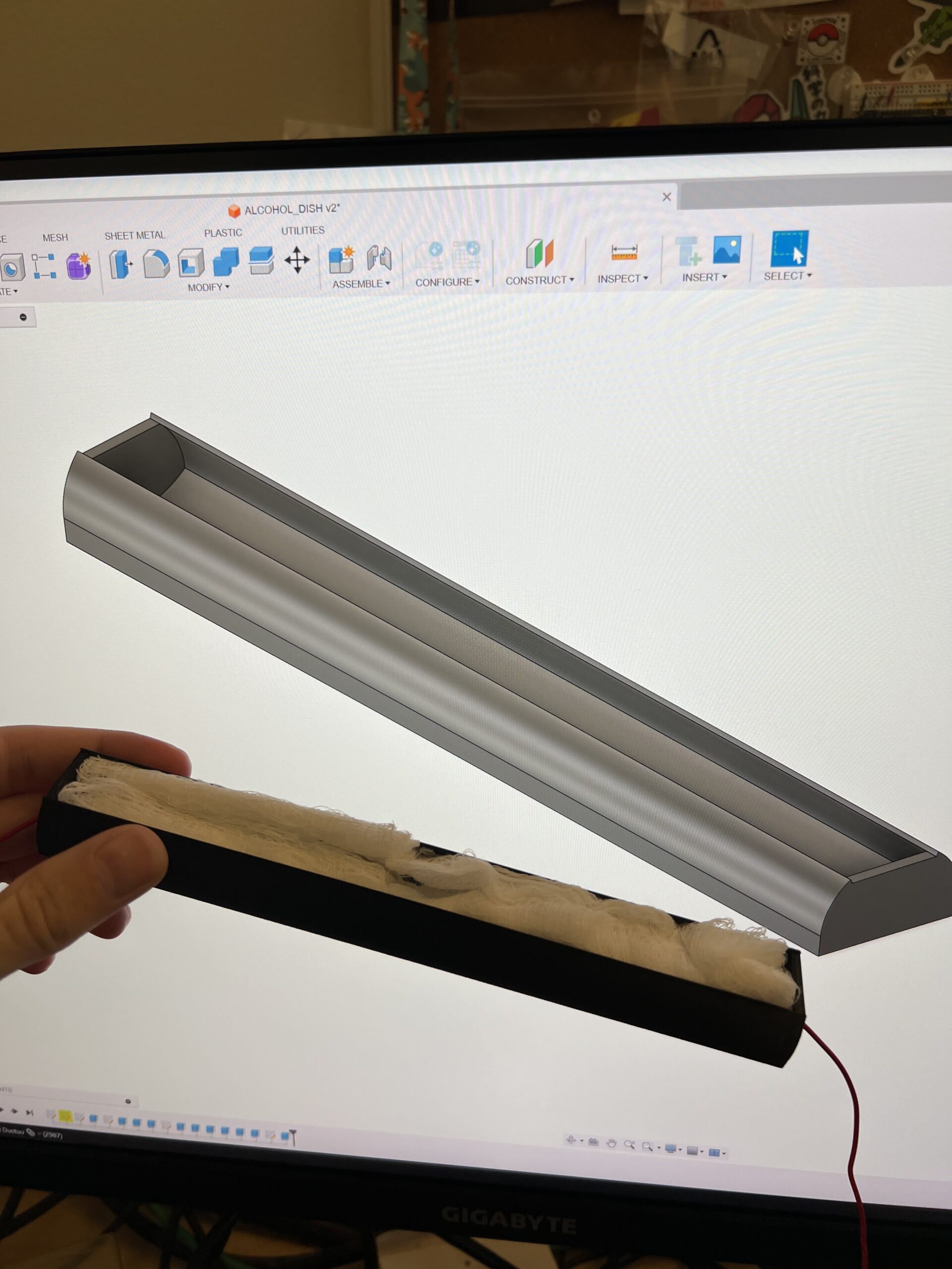
RIP alcohol reservoir. You were certainly one of the designs of all time.

Therefore, I ditched that idea and settled for a big pad of carbon fiber felt material I had lying around. Normal felt would have probably worked fine, but I just had this stuff. I hot-glued it to the top the the tank. I did make a minor mistake here though – make sure you hot-glue all of the corners really well. My felt drooped down and dropped alcohol when it was first used which was pretty disruptive.

Lights

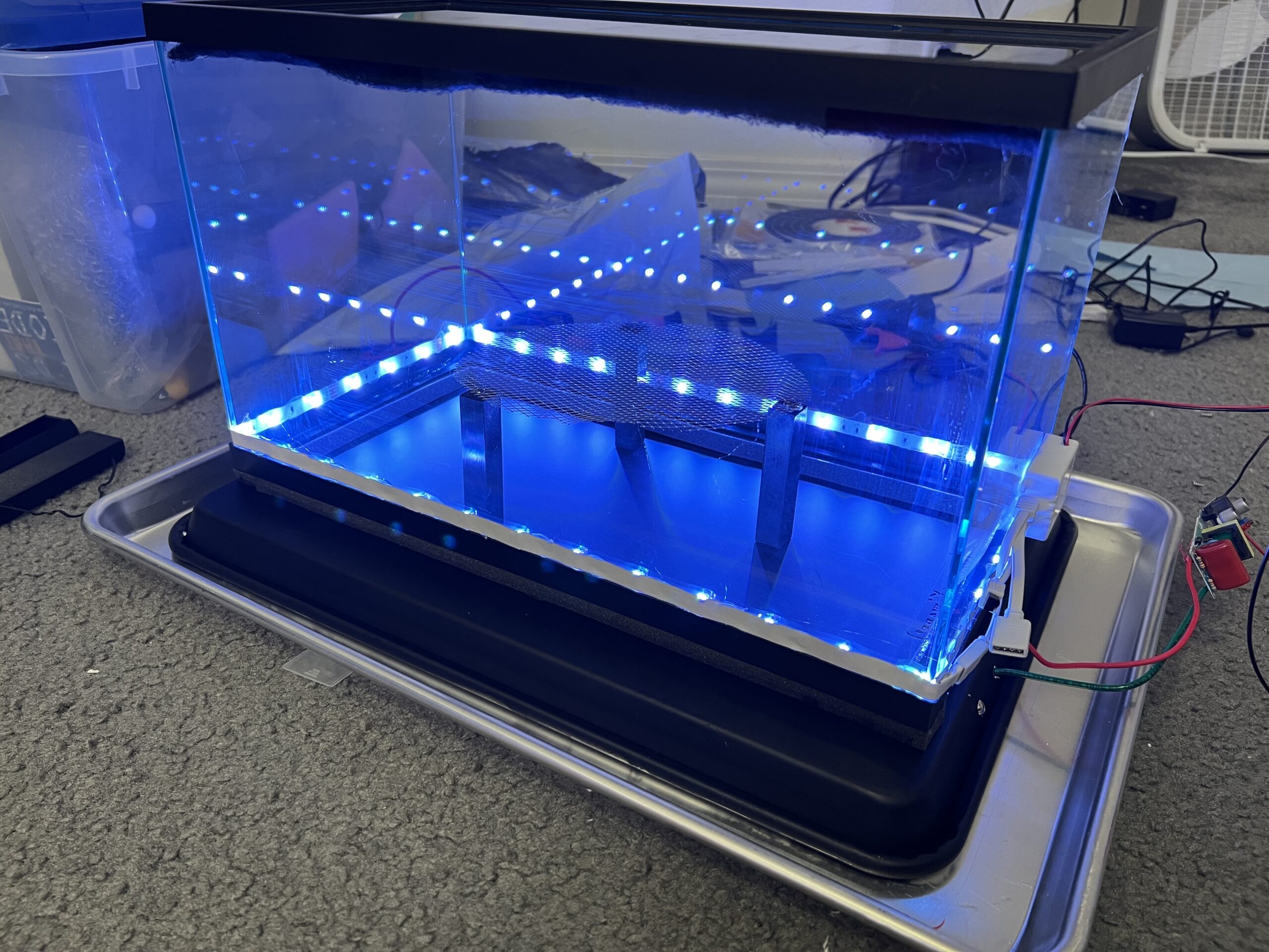
Pretty straightforward. I found a cheap kit of LED-light strips. They even came with their own little controller. They worked alright. I’d look for some better ones with a higher LED density next time. A more powerful, diffuse white light would have been ideal. While these LEDs do have their own adhesive on the back, I hot-glued them around the exterior of the enclosure as the alcohol surely would have dissolved the glue and wiring everything up properly within the chamber would have been a pain.
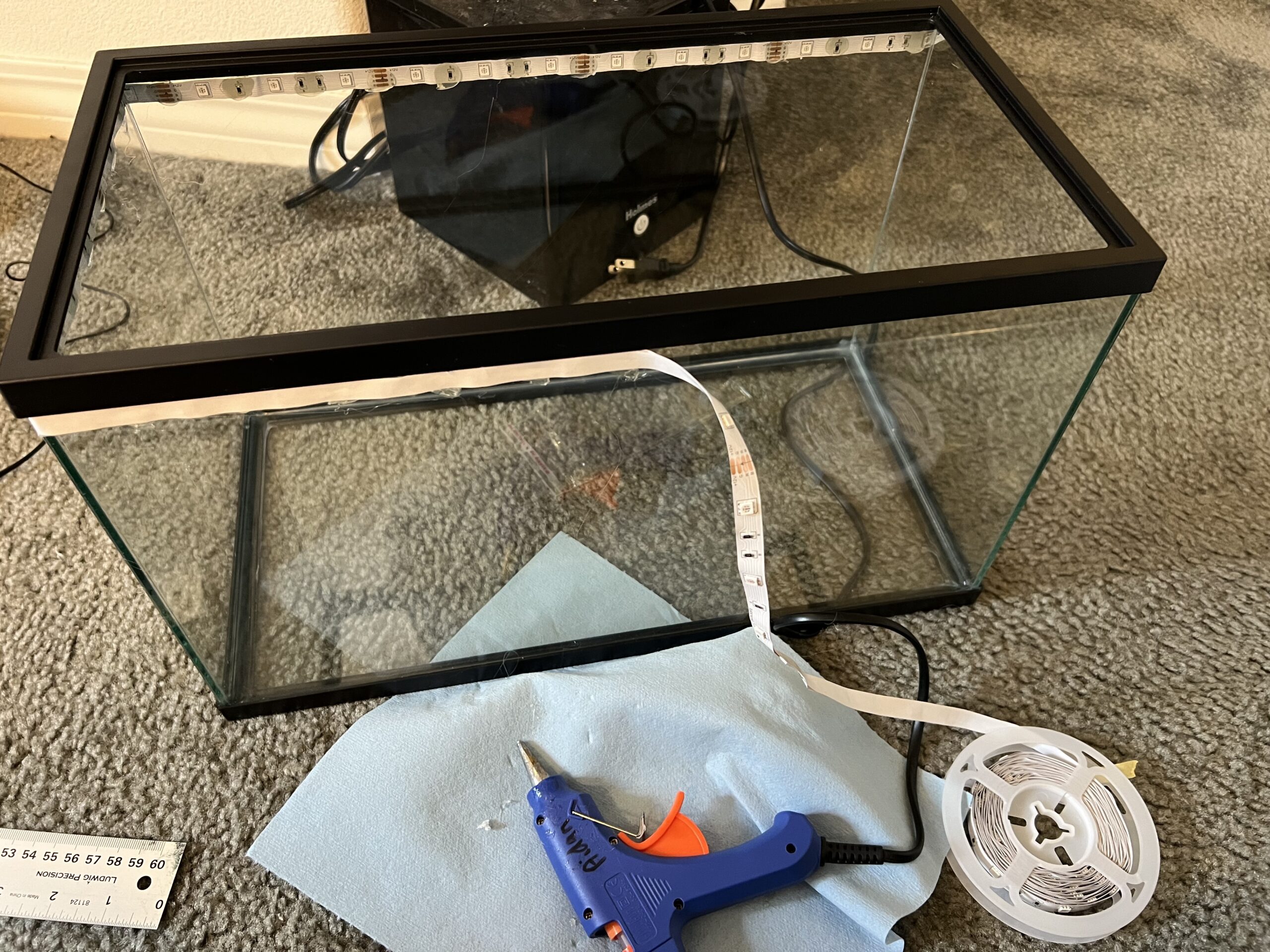
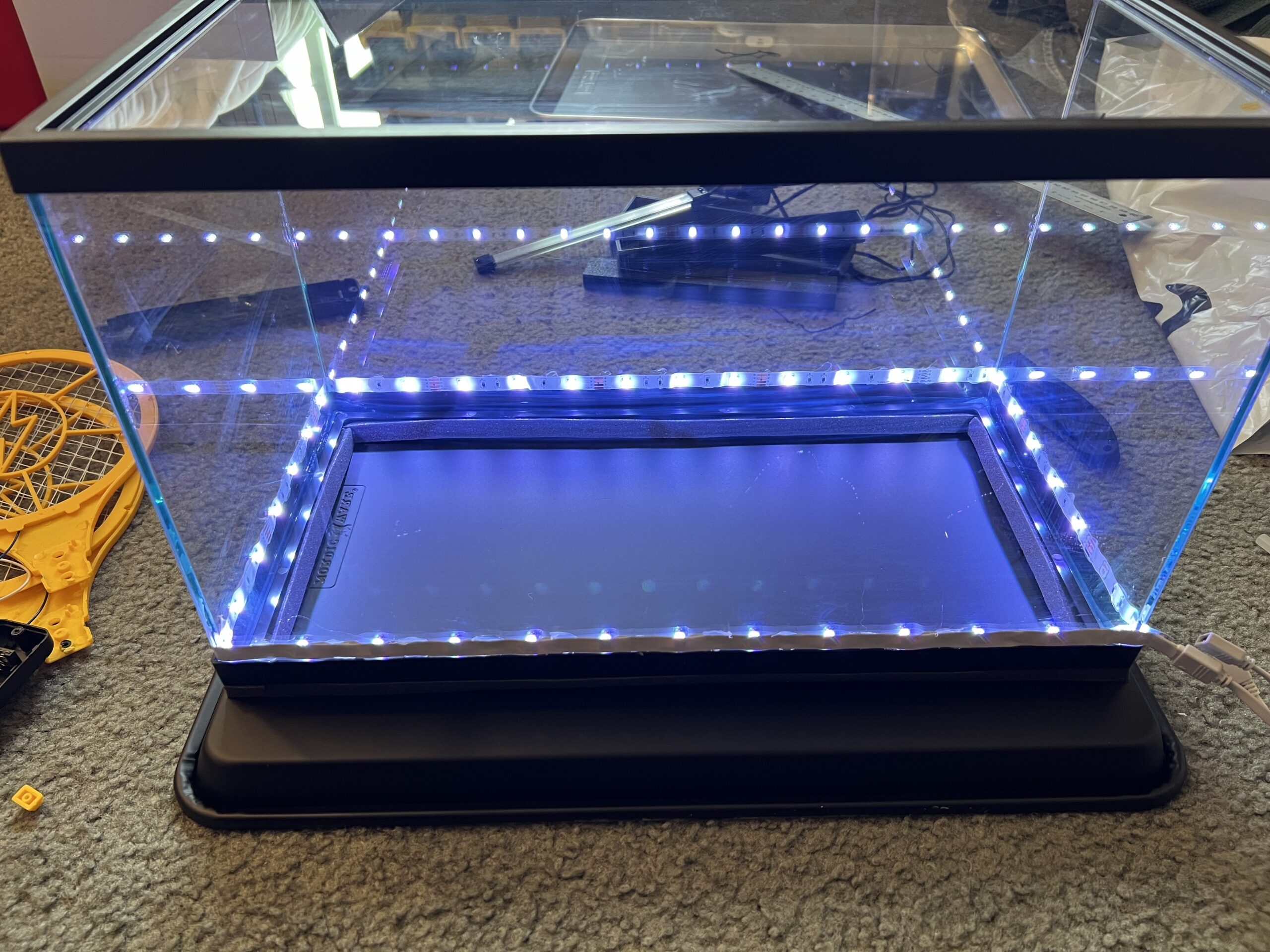
Not bad!

You may also notice that the bottom of the chamber has some foam weather stripping on it. This was a nice idea, but ultimately ended up being a mistake. For starters, it keep fusing itself to the paint of the black plate, making it annoying to lift the chamber off the plate. Second, it just wasn’t rated for the temperatures I was going to expose it to, therefore, when the plate deformed slightly under the temperature difference, the weather stripping stayed frozen in it’s deformed state, ruining the important seal from the outside air.
I ended up removing the foam and placing the tank directly onto the cold plate. Thankfully, my plate was thick enough to not deform all that much, so small squirts of alcohol around the perimeter of the tank during the experiment served as “surface-tension” seals. Not ideal, but worked fine.

High Voltage!

This part was pretty fun (and a bit nerve-wracking). Cloud chambers work best when they have a high-voltage potential between the observation zone and the cold plate. This voltage field dramatically improves the visibility of the vapor trails. So much so that it’s usually the difference between “it works!” and “damn it.” In our case, we directly observed that the positively charged alpha particles were strongly attracted to the negatively charged bottom plate which allowed us to toggle their visibility by turning the field on and off.

I know I’m spoiling the continuity of this story once again, but look how drastic the result is!


Yet again, I must warn you. Even though getting shocked by this device probably won’t kill you, it’s still a high-voltage power supply with an output in excess of 1kV. Best case shock scenario, it really hurts, worst case, you seriously injure yourself (or die), and I don’t want that to happen. So yet again, if this isn’t an area where you understand the nuances and dangers, it might be best to steer clear and not try this yourself.

I achieved this high-voltage by harvesting the high-voltage step-up board from inside of a cheap electric fly swatter. $10 bucks and I had a voltage source that would make my multimeter scream OVERLOAD (sorry little buddy, I had to try it).

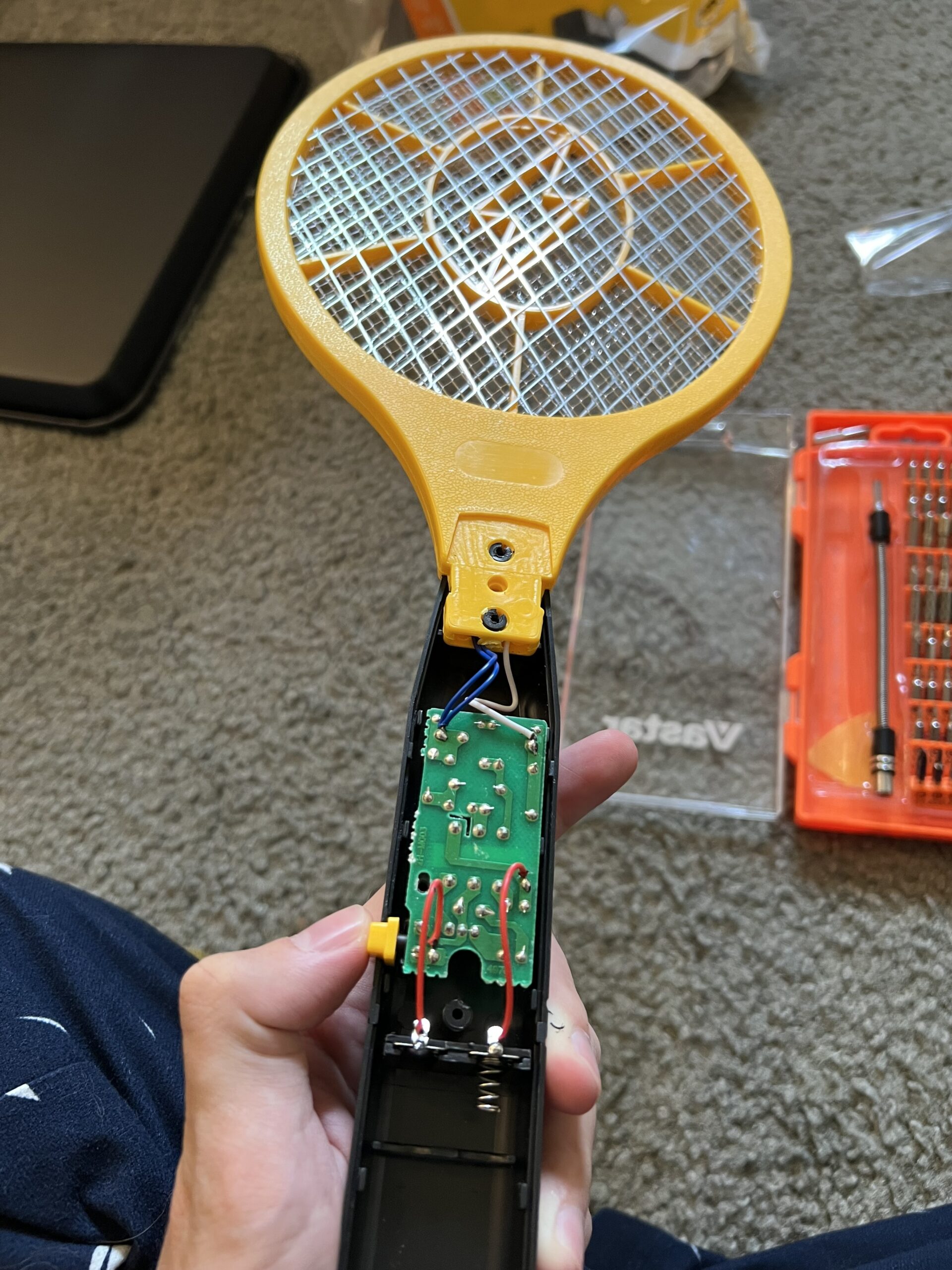
Yes, I made sure the capacitor was discharged before handling the board.

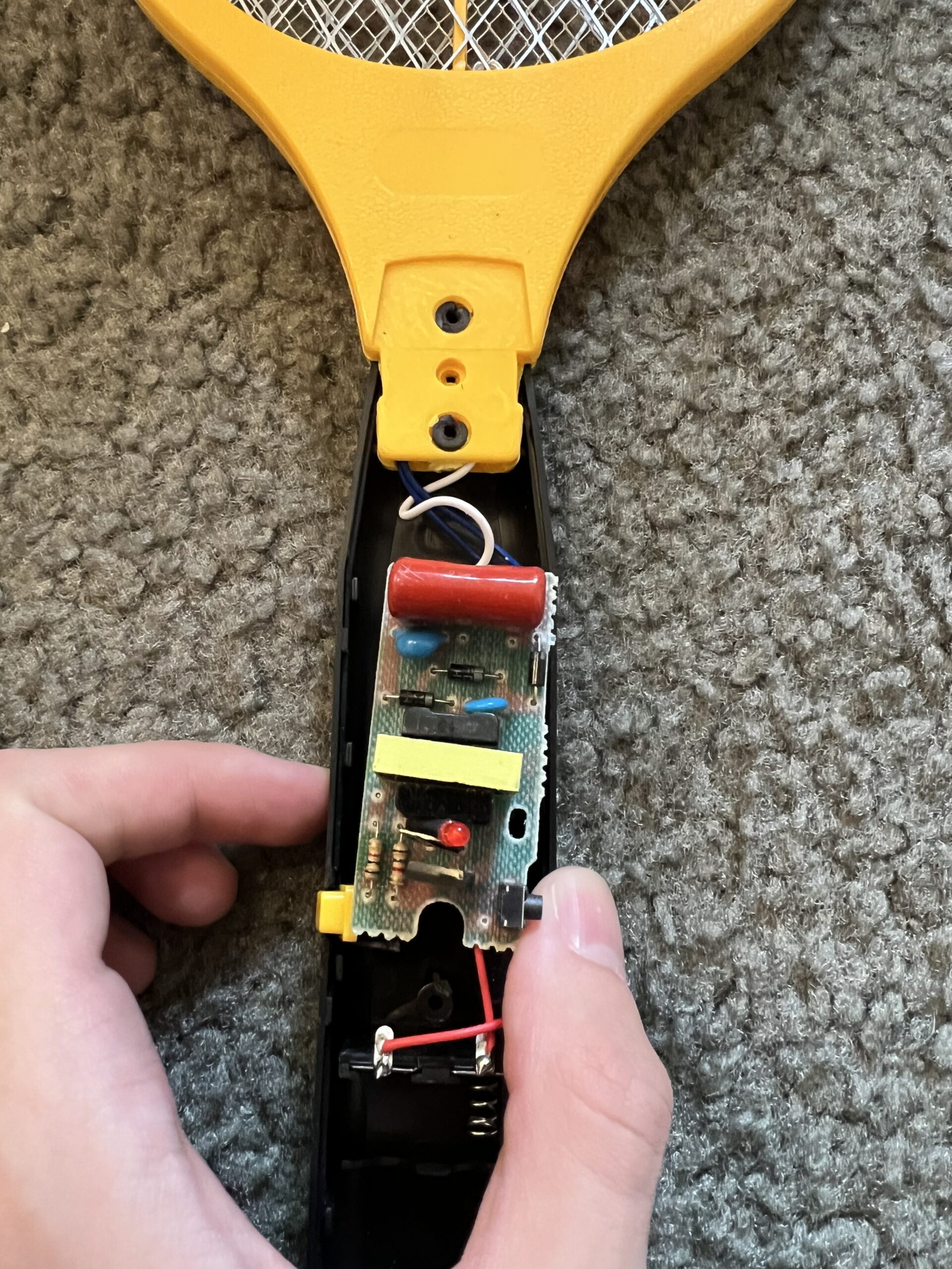
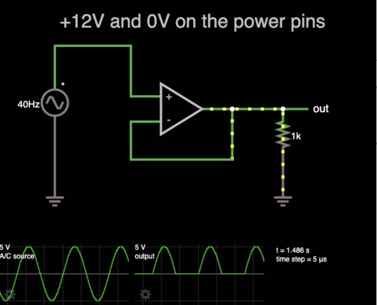
The circuit is actually pretty straight-forward. It appears that 3V DC comes in from a pair of AA batteries, then a small transistor circuit converts it into a high-frequency alternating current. That AC is sent through a transformer, stepping up the voltage dramatically, then through a bridge-rectifier to turn it back to DC. A big fat capacitor at the end stores the energy used for zapping flies (or you, if you’re careless). None of this really matters – I just think it’s neat!

I harvested the board from the swatter and took note of the output polarity. Fortunately, they seemed to be marked on the underside of the board. I’ve been told that the polarity doesn’t really matter in the context of the cloud chamber, but for safety reasons, I wanted the black cooling plate to be connected to the negative end of the supply. This should minimize shock-risk while in operation since the cooling plate will act as a big ground plane, shorting out any potential broken HV connections rather than applying that potential to me!

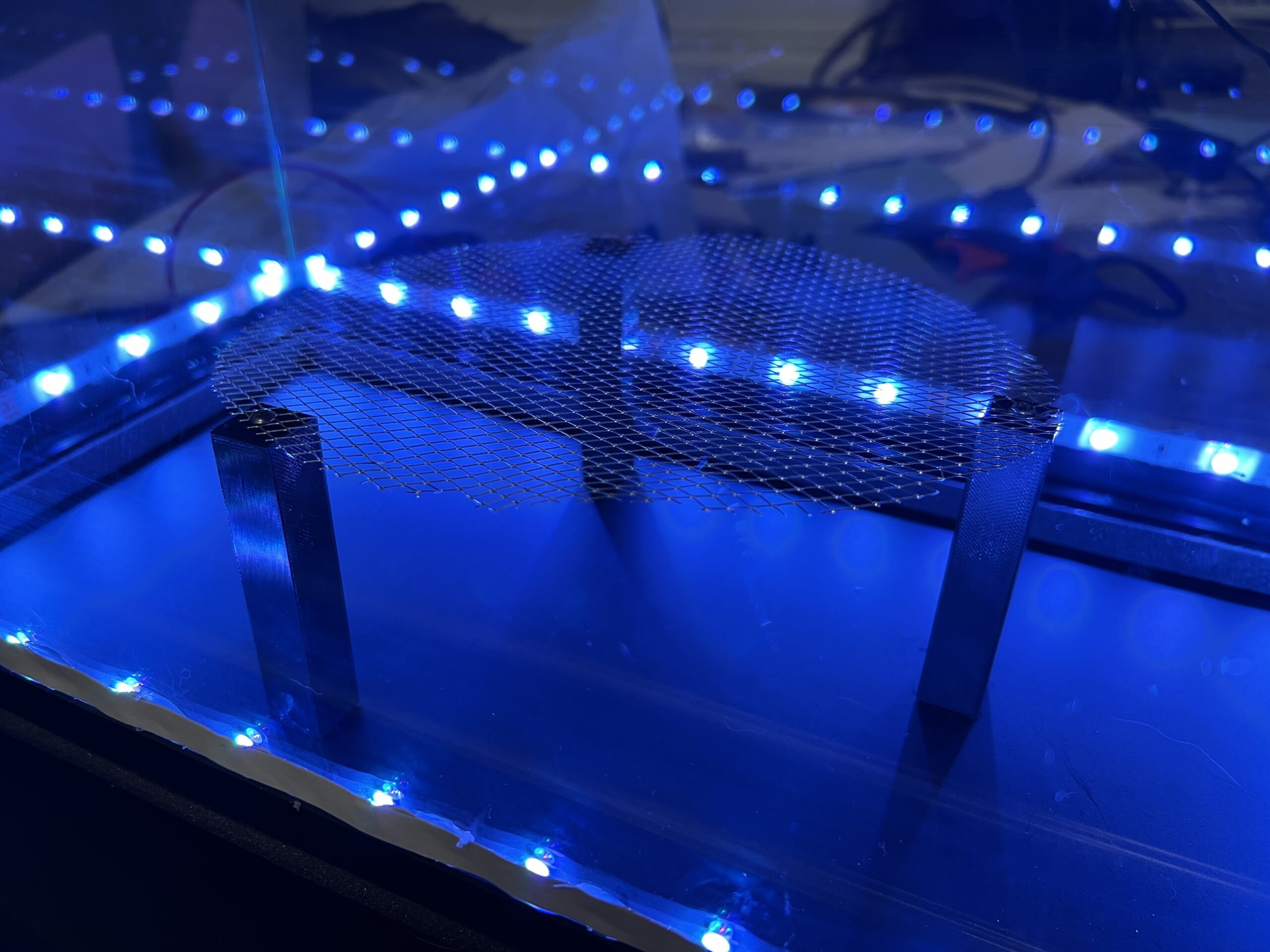
This fly swatter was also the source of the metal grate that I used to dissipate the positive charge above the cold plate.

I designed and 3D printed some simple pillars that would hold up the metal grating. They were just simple rectangular pillars with two M3 screw holes, one on each side. I also included another 3mm hole that went all the way through the pillars so I could route wires through them. I printed three of these pillars, roughly measured out their position and holes on the metal cold plate, then drilled out the holes I needed on the plate. I affixed each of these pillars to the cold plate with M3 screws, then I used more screws to hold down the metal grate. The grate actually already had a wire connected to it from the original fly swatter, so I just ran that original cable down the extra passage within the pillar it was next to. I soldered some extra wire to the bottom of the original wire, then ran that length through the bottom of the cold plate and out the side. This simple pillar design worked nicely as it provided a way to energize the grate without disrupting any seals or having cables run along the viewing area. I connected the positive end of the HV power supply to the grating. Then, I drilled a couple more holes for the negative end of the HV supply to attach to the unpainted interior of the cold plate. The negative cable had a spade connector crimped onto it and was simply attached using an M3 bolt and nut.

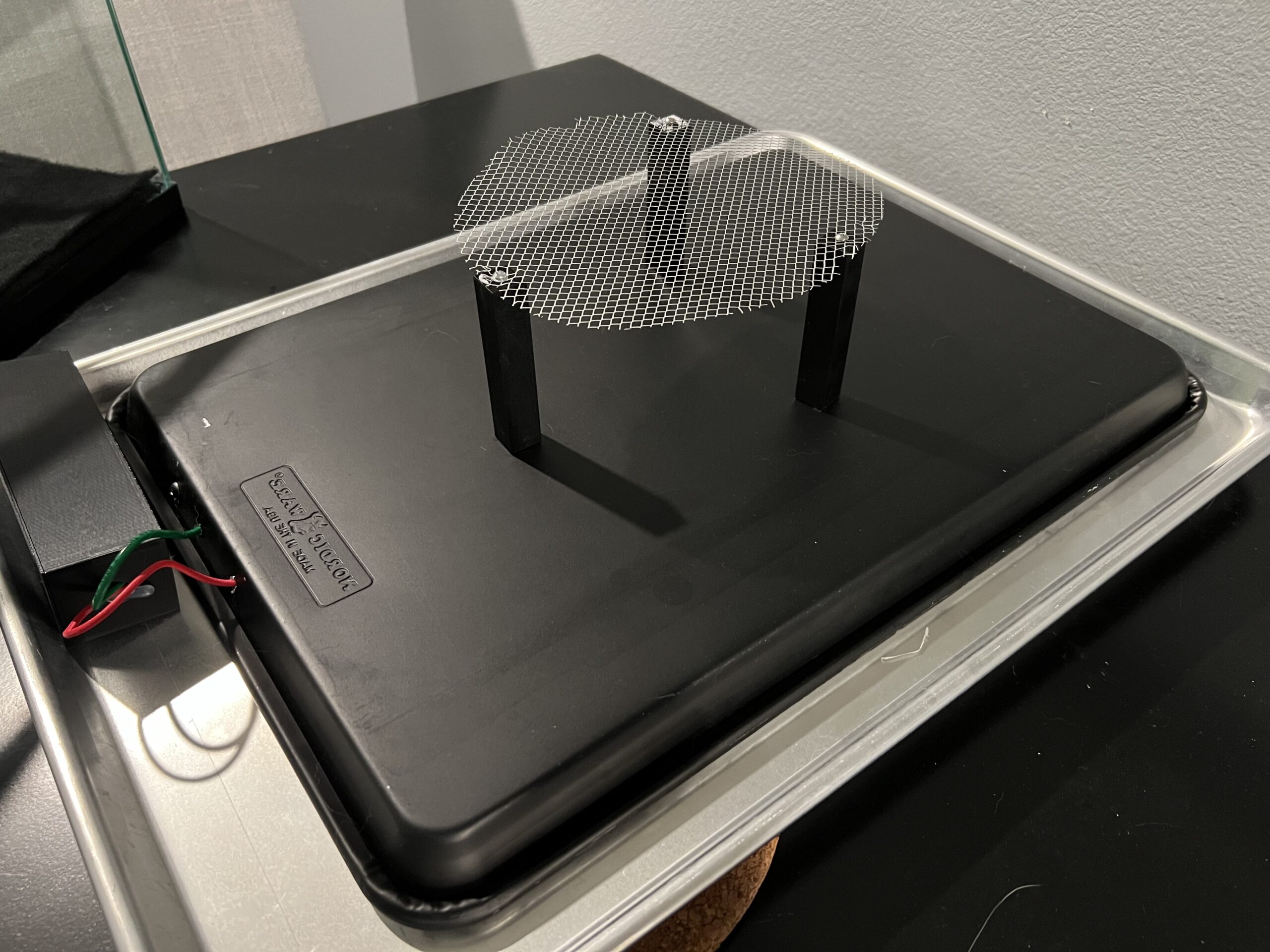
I wanted this entire project to run off of one power supply. Since the LEDs were going to run off of a 12V supply, I figured I’d just have to step 12V down to 3V to mimic the AA batteries that the swatter originally ran off of. At first, I used a linear regulator, but these swatters actually suck down about 500mA while running, so it made the linear regular a little too toasty. A simple, pre-made LM2596 buck converter set to 3V worked perfectly in this case. 12V->LED controller & LM2596->HV circuit->+output to grating, -output to cold plate. I simply popped open the LED controller and soldered some extra wires leeching off of the 12V barrel jack, then drilled a small hole in the enclosure to route the extra wires out.

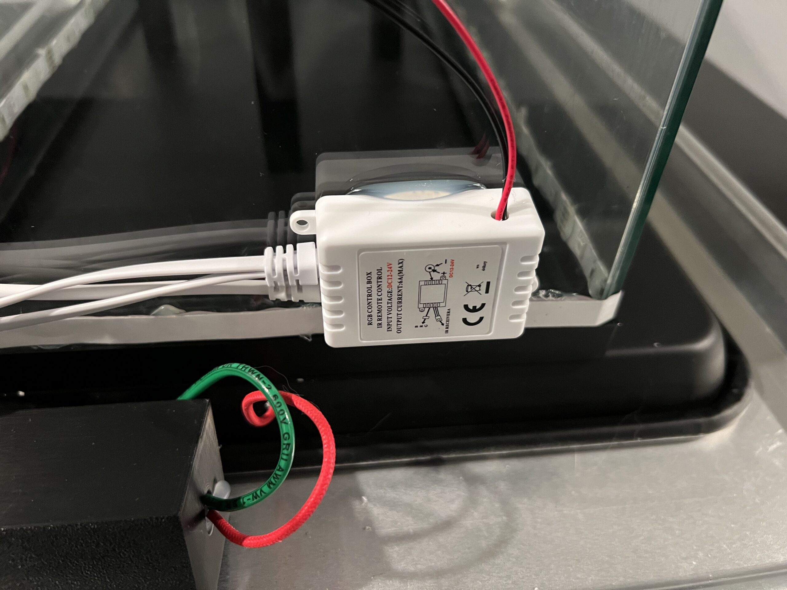
While testing, I noticed that the transistor on the HV circuit got really hot. So hot, that the entire circuit would basically fizzle out after about 1 minute of continuous use. I suppose that this circuit wasn’t really designed to stay on for longer than just a few moments. I had some spare tiny aluminum heatsinks lying around. I thermal-epoxy’d a heatsink to the back of the transistor, let the epoxy cure overnight, and boom, no more overheating issues. It went from it’s thermal junction temperature of 150°C to only about 60°C with that little heatsink.
If you’re more prone to risk than I am, you could probably remove the bleeder resistor at the end of the circuit to maintain the charge without this thing powered on continuously, but that is a significant shock-risk since the unit will remain charged even if it’s powered down until you short it out. Same goes with the massive capacitor that’s literally designed to shock – you might be able to remove it or pick a lower value cap just to sustain the voltage but reduce the stored up energy. Make sure to use HV-rated caps! I just kept the circuit as-is.

I stuffed it all into a little 3D printed box I designed that had a set of holes on each end. Once the input and output wires were in place, I hot glued the two modules down, then used more hot glue to seal the wire holes.

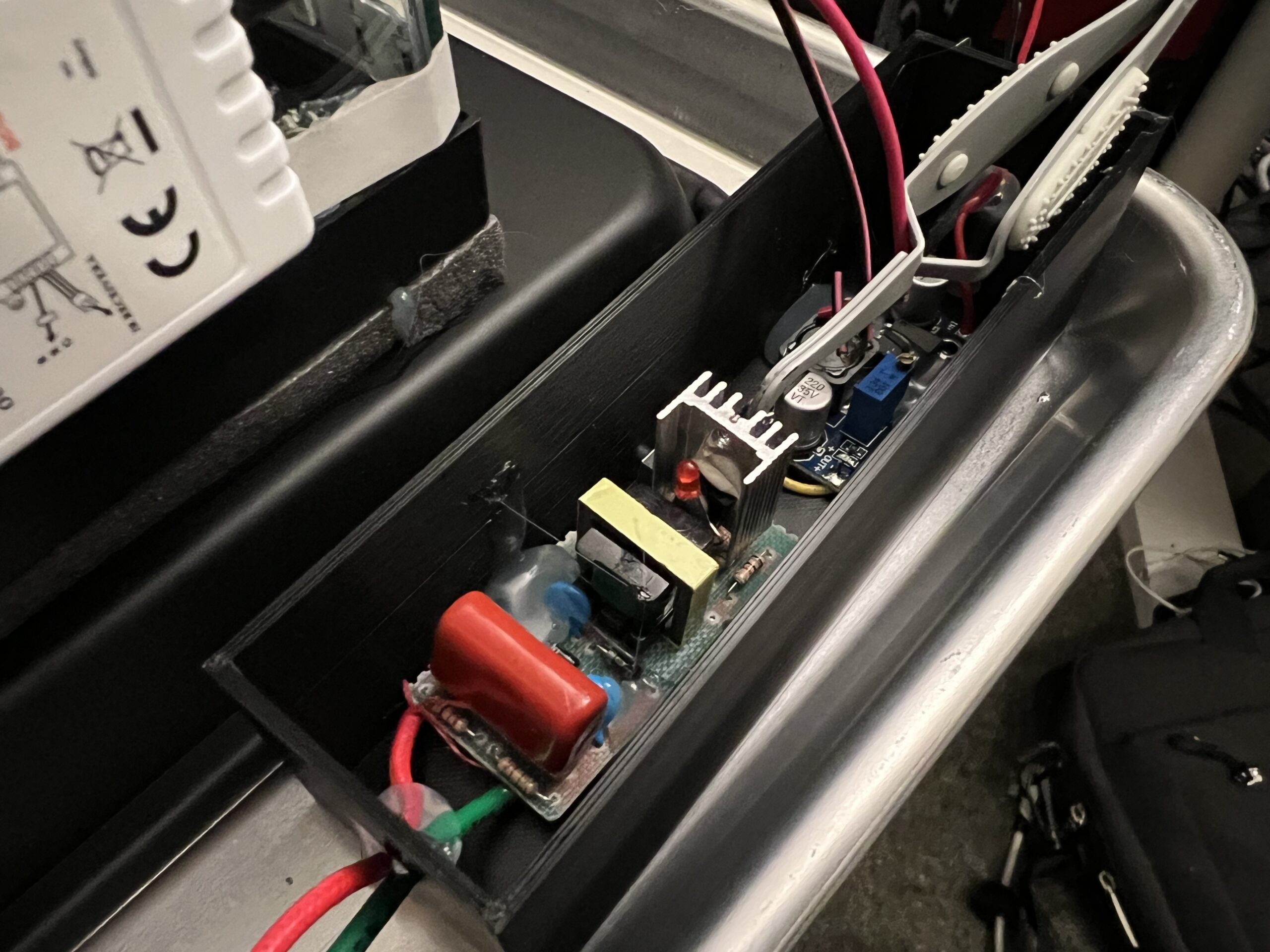
Power supply. I’m using thermal epoxy to glue a heatsink onto the primary transistor on the HV circuit.

Ready To Go

Get your resonance cascade jokes ready

Looks like a cheesy sci-fi prop

That’s pretty much it! The last step I took was to attach some felt material to the top of the tank with some hot glue. This was going to be the sponge-like material to hold a bunch of alcohol and dissipate it. Should have glued down the corners a bit better as they started to droop a bit and drip alcohol during the experiment, but it wasn’t so bad.

The last component I needed was Dry Ice. I didn’t think it was going to be that hard to get my hands on dry ice, but as it turns out, it was very tricky! I called about 8 different grocery stores asking if they stocked dry ice. 6 of them did not, 1 was out of stock and the last one said they had just a tiny bit left… all the way across town. One big trip later and I had a nice chunky 7 lbs. slab. Perfect!

I drenched the felt in the chamber with 99% isopropyl alcohol. After, I seated the dry ice onto the foam. I then placed the cold plate on top of it and listened to the block loudly protest and squeal as the metal quickly cooled down.


At first, I thought this dry ice block would only get me a half-hour or so of fun. Not the case. I probably could have had this running all night and would have still had a nice chunk left. Dry ice sublimates far slower than I anticipated with a large heat sink on top of it.

Also, one last warning, dry ice is very cold, but it’s ability to make thermal contact things like your skin isn’t very good. It’ll still get ya’, but you have to make really good contact with it for a short time. Chilled alcohol though is like cryogenic napalm. This stuff is almost sticky in a sense and is extremely cold. You simply must wear gloves at all times as you will make contact with the alcohol when handling things. If it touches your skin, it’s almost an immediate frost-bite. With the nitrile gloves, it’s still pretty nippy, but at least it doesn’t stick to your skin and you can maneuver the glove quickly to eliminate contact with your skin. I got myself a couple times and it certainly doesn’t feel very nice – thankfully it seemed like I didn’t really sustain any real damage.

Carrying on…

Quickly, the chamber cooled. I placed a gallon bag of warm water on top of the chamber to increase the ambient temperature of the alcohol on top to help it evaporate better. Soon, waves of alcohol condensate began to form near the surface of the cold plate. Colder.. colder…
Suddenly: ZIP! ZOOM!
IT WORKED. At some seemingly arbitrary point as the plate cooled, streaming particle vapor trails zipping through the chamber suddenly became visible. Wow. I can’t believe this worked on the first try.

On our first test, we placed the smoke detector source directly onto the cold plate facing up as well as a small neodymium magnet on the off chance that we observe stray beta particles being curved by it. Immediately, you could see a small shower of particles.

A weak stream of alpha particles visible from the source seen as the faint trails below the source.

After about 5 minutes though, they seemed to disappear completely. What gives? Perhaps it was the direction of the source itself? It was facing up after all. I know you can pop the little Americium button out of the surrounding chassis, but I would rather not in this case.
I made a small foil stand to hold the source roughly perpendicular to the cold plate. Yeah, you could see some particles if you looked closely enough, but it didn’t seem to be as strong as before.


Still though, you’d occasionally see a big fat trail left by another naturally decaying nuclei in the air. Combined with the hypnotizing alcohol vapor waves, it was very zen. Like an ionizing lava lamp with special events every-so-often to gawk at and exclaim, “ooh look!”
In retrospect, I think the foil stand for the source was a bad idea. It likely became charged within the HV field and attracted most of the particles towards itself, preventing them from being visible in the fog.

Eventually though, we discovered the big issue with why we weren’t seeing as many trails from our source. Alcohol and/or water had made it’s way onto the source, likely through condensation. Water is excellent at absorbing radiation. So much so that massive water pools are employed to shield from radiation in industrial settings like spent fuel pools and irradiators.

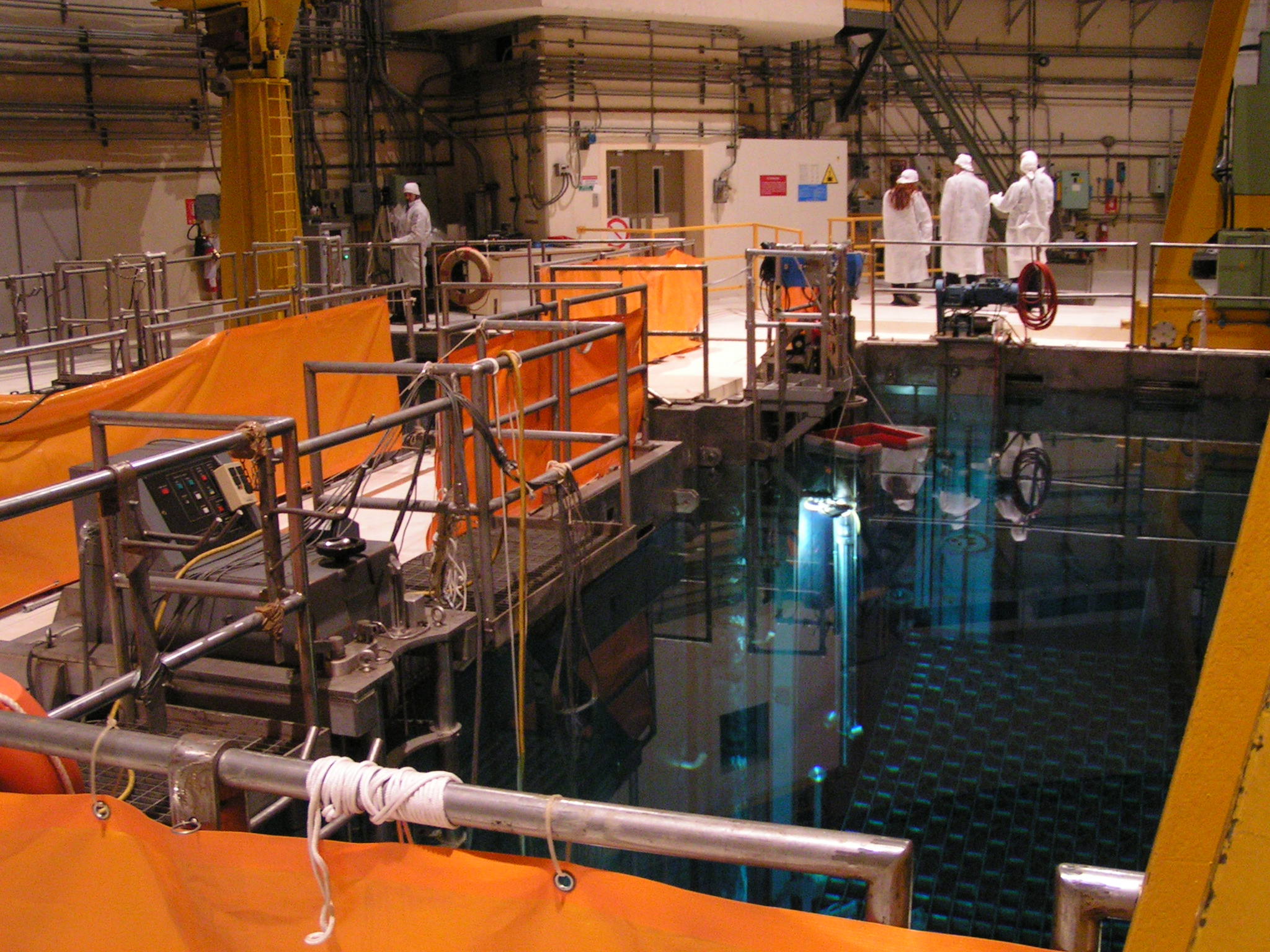
Image credit Simone Ramella. An example of a spent-fuel pool filled with water to cool spent nuclear fuel and to shield workers from radiation.

In our case, the alpha particles had so much trouble making their way through whatever liquid was covering our source that a nearly imperceivable drop of it was preventing us from visualizing anything. After drying-off our source, alpha particle vapor trails immediately became visible again. Awesome!

What followed next was an amazing example of organic discovery. I still wanted the source’s output to be facing the cold plate, but I didn’t want to involve my crude foil stand anymore. So, I just placed the source face-down on top of the HV grid.
Instantly, we saw a massive shower of particles. This was the absolute best result we had seen so far. You could clearly see a huge plume of particles emanating from this tiny source. This was quite impressive for an alpha source as alpha particles tend to only travel a couple inches or so before being absorbed.


A friend of mine who was watching along with us hypothesized that the difference in charge between the source and cold plate could be attracting and accelerating the particles, extending their apparent range. We decided to try turning the electric field on and off to see what would happen. Yep, turns out, that’s exactly what was happening!


I’m most definitely putting “accidentally created a particle accelerator out of a fish tank” on all future resumes.

Conclusion

This project was mesmerizing and very satisfying to build. I found it fairly simple to throw together and was shocked at how well it worked on the first try. I could have watched it all night.

If I were to try this again, I’d go with a far smaller scale. The size of the chamber was pretty neat, but at the end of the day, it’s a big, bulky thing that I now need to find space for. I’d also like to avoid using dry ice again. As fun as dry ice is to play with, it was a major pain to find and was inconvenient to transport. I’d like to try this again one day with a much smaller design that uses peltier elements and a large heat sink instead. Peltier elements, despite being fairly inefficient, can transfer enough heat to create the cryogenic temperatures needed for a device like this. With the right design, all I’d need to do is add some alcohol, flick a switch and boom, things get cold and vapor trail-y.

The small scale would also make it easier to create a more robust seal as it means less chance for metal plates to dramatically flex under the temperature difference.

Next up, I’ll be exploring some fairly simple gamma ray spectroscopy with a new device I have coming in soon. The Radiacode 103. This device uses a scintillation crystal instead of a geiger-muller tube to detect gamma rays. While this device is far more expensive than my dinky BR-6 geiger counter (by an order of magnitude lol), it is far more sensitive and far more capable. This tool will allow me to identify radioisotopes based on their energy signatures, measure radiation intensity with far more precision and even log ambient levels of radiation on a map. Super cool! Can’t wait to try it out.

Audio Mixing, Big Class D Amps, and Light Shows

July 21, 2020

Strap in, big post.

(If you just want to quickly see the project working, click here)

I’m fascinated by audio electronics. Arthur C. Clarke’s quote, “Any sufficiently advanced technology is indistinguishable from magic,” really does become relevant when developing analog circuits. While digital circuits can also be challenging at times, their trouble-shooting is generally constrained to “working, or not working.” Analog circuits, especially audio circuits, are crafted out of components that exploit the fundamental physical properties of various materials and are entirely dictated by often complicated mathematics and theories. You are at the mercy of seemingly arcane and arbitrary phenomena that permeate every facet of our existence. I often stop and marvel at the madness happening on my workbench when working with analog circuits. Magnets, coils, resistors, capacitors, amplifiers – a big jumble of crazy things all working together, doing their little parts applying their unique properties to condition signals suitable for other components or the end user. It’s all endlessly fascinating to me, and I thought I’d share my appreciation for those who also feel the same way.

I write this article today to share with you a new audio project I’ve been working on, as well as give some insight into the things I learned along the way. I’ve never received a formal education in electronics engineering, so I feel as though my naive perspective may in-fact be of use to those who are also at my level of understanding. In my opinion, the most of the difficulty in designing anything is going into the project without knowing of the names and techniques used by your not only your contemporaries, but the great minds from a century ago. Once you have a searchable term that you can plop into Google, the mysteries quickly solve themselves and the fog begins to clear. Also, as I’ve found, fundamental concepts that are simple in theory may take a little bit of time to wrap your head around as prerequisite knowledge is often assumed, even though the reader may not have those building blocks under their belt yet. Hopefully, I can convey what I learned in a way that makes sense to novices, even though what I will be talking about is fairly complicated.

Anyways, enough rambling, let’s get to the project…

Boombox Mascot

This project began when I was contacted by a person I worked with previously. They are starting up their own children’s TV/web show and wanted to create a custom “boombox character” with lights, speakers (duh), and a screen acting as their “face.” Admittedly, this did sound a bit silly to me at first, but truthfully, I’ve grown very fond of this project. At this stage in the game, I’ve only developed the audio and light-show portion of the character, but I feel that it is by far the most fascinating aspect of the project. You won’t see much, or any of the character itself in this post, simply the audio and lighting electronics, but I digress.

I didn’t have much to go on specification-wise. All I knew is that I’d require a mixing circuit to handle multiple audio inputs, a power amplifier to drive some 5″ speakers, and a way to sample the audio stream to create a reactive light show. Board and component size was not really an issue as the custom enclosure will be fairly large.

That ‘specification’ above was all I really had to work with, so I decided that my first task was to select some of the main components, like the speakers, so I could have some solid numbers to work with.

Here are the things I thought about before I began:

  • The boombox was going to be in stereo.
  • There will be four speakers in total to drive. Two tweeters handle the high frequencies, two mid-range speakers to handle just about everything else. All speakers will be 8 ohms to keep things simple.
  • No subwoofer on this design, but keep one in mind while designing just in case you’d like to add one later.
  • The amplifier had to be powerful enough to drive my speakers with a reasonable volume level, but since the speaker specification was fairly nebulous at the time, I needed to choose an amp that had the power head-room to support more, or bigger speakers, just in case the project changed over time.
  • I wanted the amp to be fairly efficient, as dealing with a ton of heat would just be another engineering hurdle.
  • This is not a “critical listening” device, meaning audio quality does not need to be absolutely pristine. Subjectively sounding good is the goal. Objectively sounding good is something that I’ll leave to the audio engineering professionals.
  • I needed a way to control addressable LEDs. I think a Teensy board should be more than enough to handle that while simultaneously sampling the audio stream to perform some neat tricks, like fast-Fourier transformations or VU metering.

With those ideas in mind, I began breadboarding.

Getting an Early Feel for Things

I’ve worked with audio stuff before, of course, so I had a rudimentary idea of what I was doing, but I have never worked on audio circuits with this much power behind it before. 5″ speakers are still fairly big components and they can take a ton of power to drive correctly. Before I committed to purchasing any big speakers, though, I decided to make a few lower-powered prototypes with some smaller, but still fairly beefy speakers. I picked up a couple of 2 inch, 5 watt, 4 ohm speakers just to test with and began developing some breadboard circuits.

Picking a Power Amplifier

Picking an amplifier class was also on my mind at this time. For those who don’t know, there are several audio amplifier classes, each with their own unique properties. Some of the most common are Class A, Class B, Class AB, and Class D. There are others, but I’ll quickly go over these ones.

Class A amps are usually found in systems where quality is more important than efficiency. Therefore, they have a tendency to consume quite a bit of power and get really hot. Class B amplifiers were designed to improve efficiency at the expense of some potential distortion issues at the signal’s “zero-crossing” (the point where the audio signal nears 0V).

As a means to combine the improved efficiency of Class B amps and the minimal distortion of the Class A amp, the class AB amplifier was invented. Class AB amplifiers are extremely common and provide a good middle-ground between A and B class amps. Unfortunately, at higher powers, Class AB amplifiers still have a tendency to get really hot and require beefy heat sinking.

Finally, there’s Class D amplifiers. Class D amplifiers are extremely efficient. Like… extremely extremely efficient, to the point where it kind of feels like cheating the laws of physics a bit. Class D amplifiers work on the principle of filtered high-frequency pulse-width modulation driven transistors, similar to a how a switch-mode power supply boosts up voltages, but these devices are for audio signals. I’ll explain more in detail in just a bit since there’s a bit of technical jargon there. The switching frequencies at which these amps operate at are well above the range of human hearing and are therefore inaudible should the circuit be designed correctly. The upshot of this design is a versatile amplifier capable of extremely high power levels with unbelievably low waste heat. Class D amps can theoretically reach 100% efficiency, though, in the real world, you’ll usually see them near the 85-95% range. Their downside? Due to their switch-mode design, Class D amps have caught a bit of a bad wrap from the high-fidelity crowd. With a Class D amp, you are essentially filtering and ‘averaging*’ the voltage of a bunch of sharp square waveforms, so the output waveform will never be absolutely pristine. But… to be totally honest, the output quality is good enough to the point where you’d be really hard pressed to hear the difference if your circuit is designed correctly. Class D amps, as we’ll discover, are also fairly picky and can be difficult to keep stable. Effective Class D designs truly are fantastic though, and their versatility and efficiency is why they’re becoming the de facto amplifier component for many new products.

*Not exactly averaging per se, but you get the idea.

I mentioned pulse-width modulation in the paragraph above. I’d like to clarify a bit on the subject just in case the reader has never heard of it before.

Basically, PWM is a technique where you approximate voltages with a digital circuit using on-time, and off-time. Remember, a digital device can only produce two discrete voltage levels, HIGH, and LOW. There is no “in-between.” Those “in-between” voltages are important for analog signals, like audio, as those distinct voltages are where the information is. Analog in this context simply means “no discrete steps. Infinite resolution between points.” The higher the voltage, the more the electromagnet in the speaker cone repels the permanent magnet in the speaker base, moving some air, which we perceive as sound, and vice versa for negative voltages. With PWM, we can allow digital devices to approximate those vitally important “in-between” voltages and create an analog signal.

PWM creates a series of square waves, meaning the voltage level of the wave goes to it’s maximum point and minimum point (HIGH and LOW), with no voltage levels in between. By changing the ratio of HIGH time to LOW time, we adjust what is known as the “duty cycle.” The more time the PWM signal spends at the HIGH voltage, the higher the average voltage will be. The approximate DC voltage can be calculated simply by using D*V (D = Duty Cycle, V = peak voltage, AKA what ever our HIGH level is).

If our peak voltage is 12 volts, and our duty cycle is 50%, we would calculate the average voltage to be: 12*0.5 = 6V.

If our peak voltage is 12 volts, and our duty cycle is 14%, we would calculate the average voltage to be: 12*0.14 = 1.68V.

If our peak voltage is 12 volts, and our duty cycle is 80%, we would calculate the average voltage to be: 12*0.8 = 9.6V.

You see, by adjusting the duty cycle, we can achieve a synthetic analog voltage using only digital signals.

Once we achieve the voltage we’re looking for, we can filter the square-wave to remove any harsh high-frequency signal edges that may make it into our synthetic analog stream. Think of the filter circuitry as some sandpaper to smooth out the rough edges of our signal. PWM can be found in just about everything “adjustable” nowadays, from your light dimmer, to an electric car’s speed controller, to synthesizers. If you ever hear a weird high frequency buzzing coming lights or motors, that is probably the PWM duty cycle you’re hearing!

An example of PWM (labeled PDM). Notice how the longer periods of HIGH voltages on the blue square wave correlates to a higher voltage on the green analog wave while longer periods of LOW voltages drop the green wave down. Image source.

Okay, we get it. Class D is Pretty Neat-o

As you’ve probably guessed by now, I’m going with a Class D amp. They’re efficient, they’re powerful, and they’re versatile. How in the hell do you get one to work properly though?

Sadly, getting Class D amps to work on a breadboard is fairly tough. Remember, we’re dealing with high-frequency analog magic here, so stray capacitance, spaghetti wiring, and components mashed together in every which direction makes a dramatic impact on performance. The Class D amps I work with require fairly pristine electrical conditions to work in or else they become unstable or wont operate at all. I decided to give it a go anyways just for a proof of concept.

For my low-power proof-of-concept circuit, I went with a 15W/ch TPA3122D2 Class D amp. It’s the only DIP, stereo Class D I know of, and I’ve used it before, albeit, with questionable design decisions in retrospect. It should be good enough just for testing. I’ll chose a much more powerful 140W Class D for the final circuit, but we’ll get to that later.

The first circuit was fairly simple in concept.

Audio input -> pre-amplifier -> power amplifier -> speakers AND have the Teensy microcontroller sample the audio to create a little light show.

Pre-Amplification

For the pre-amplifier, I was simply going to use a biased unity-gain op-amp.

If you already understand the concept of “biasing” and “DC offsets,” feel free to skip this section by clicking here, otherwise, read on!

More technical jargon, allow me to explain, as this concept took me a little bit to wrap my head around too, even though it’s fairly simple. A unity-gain op-amp’s job is simply to “buffer” the incoming signal. It will one-for-one match the input voltage level and provide no gain, therefore, no amplification. What’s the point of a unity-gain op-amp if it doesn’t amplify anything? For one, it gives the audio source one degree of separation from the rest of the audio circuit. More importantly, the incoming signal source doesn’t need strain itself at all in order to drive the main amplification circuit. The op-amp doesn’t sink any current* (ideally) from its inputs and only samples the signal voltage, essentially producing an isolated equivalent output on the other end. This way, it doesn’t matter if your signal source can provide 1000mA of current, or 10 mA, the voltage is all that matters and the signal source remains unloaded.

As for biasing, this is also a fairly simple concept that gets taken for granted and is therefore often skipped over when explaining a circuit. Basically, an op-amp can only produce output voltages between it’s positive power supply voltage pin and negative voltage supply pin. Op-amps can, in fact, happily handle fairly large input voltages and negative voltages on their inputs, which is somewhat uncommon to see when you’re used to digital circuits that tend to hang around the 1.8-5V range.

TL;DR: A bias is simply (your signal + a voltage). It allows you to shift a signal up. It is a “DC Offset.”

If you had the positive power supply pin of an **ideal** op-amp hooked up to a +15V supply and the negative power supply pin hooked up to -15V, you can produce any voltage on the output between -15 and +15 volts. “Ideal” is heavily emphasized, as most op-amps are not rail-to-rail (able to hit exact supply voltages), let alone ideal. Therefore, you’re looking at around +/-14V worth of room to work with depending on the op-amp, which is still more than enough for what we’re doing.

Normal audio signals will almost always center around 0V, meaning they will have positive voltages and negative voltages. “Line level” is generally 3 volts peak-to-peak, though particularly hot audio sources can sometimes go all the way up to 6 volts peak-to-peak or more. 3 volts peak-to-peak meaning the signal’s highest point will be around +1.5V and the lowest point will be around -1.5V, the distance between those two peaks would be 3V. With an op-amp that has access to +/-14V, we have plenty of room to recreate our signal.

A unity-gain op-amp with a +/-15V power supply (power supply pins not shown). Input signal is 5 Volts, peak-to-peak. Notice how the input signal is perfectly recreated on the output at the bottom of the image. 1K resistor is just to load the circuit.

Here’s the problem though, bipolar power supplies that can supply negative voltages are actually surprisingly uncommon and tricky to find unless you’re willing to create your own DC/DC circuit or transformer-based power supply, therefore, we usually only have positive voltages to work with.

Let’s assume our op-amp is now supplied with +12V on the positive power supply pin and 0V on the negative supply pin. If our audio signal produces any voltage between 0V and 11V, we’d be totally fine. The problem is, as mentioned before, normal audio signals will produce negative voltages. We cannot produce any voltage lower than 0V on our op-amp, therefore, the signal is “clipped,” and the result is heavy distortion. Half of our waveform is now gone, which is obviously no good. How can we use a unity-gain buffer with a single-voltage power supply? Biasing.

12V and 0V power-in, same 5Vpp input. Notice how the top of the waveform translates over fine, but the bottom half is cut off at the 0V line. Since we don’t have a negative supply, we can’t produce any voltage under 0V!

What if we could make the input signal ‘zero-cross’ at 6V instead of 0V?  That way, we have 6V on each side of the waveform to work with instead of +12V in one direction. That is what biasing does.

Basically, all we’re doing is shifting the input wave up a little to make sure it stays within our valid voltage range. We can create a rudimentary bias voltage by simply using a voltage divider to split +12V in half. Two 10K resistors in series to ground will produce +6V in the middle when connected to +12V. Then, we simply connect that +6V to our audio signal source through a high-value resistor (1M does well), and boom, biased op-amp. Adding a couple support components like capacitors will help with stability and blocking DC.

12V & 0V supply, but this time with a 6V bias on the input signal. Notice how the output waveform is no longer clipped at the thick grey 0V line and has been shifted up. (Ignore the misleading graph scaling, the AC voltage is basically untouched. Notice how the voltage-per-division boxes are stretched differently.)

Blocking DC? Yep, we’re not done yet. DC voltages are extremely undesirable for audio circuits. Not only do DC voltages have the ability to accidentally bias components that aren’t expecting it, but they can burn out your speakers! DC voltages should be isolated and avoided at all costs. But wait, we just introduced DC voltage directly into our circuit via our bias circuit. How do we get rid of it and return to an unbiased, 0V zero-crossing AC signal? DC blocking capacitors. Capacitors will block DC and will only allow AC to pass through them. Therefore, in this example, adding a 10uF capacitor to the output of the op-amp will remove our DC bias and leave us with a perfectly buffered signal with no distortion.

Notice how the 10uF cap on the end shifts the AC voltage back down again. (Again, please ignore the misleading graph scaling. An RC filter was formed in this simulation, but is unrelated to the point, ignore the slight voltage drop.)

ALL OF THIS TO SAY…

Again, a bias is simply (your signal + a voltage). It will shift up your signal by the voltage you apply. Then, you can remove that shift up with a DC blocking cap. Phewph.

By the way, those simulator schematics above are kind of janky and were only required to make it work. Here is the actual circuit I used:

The way I would bias an unity-gain op-amp with a +12V power supply. R1-R3 divide 12V/2 to form 6V. R2 prevents R3 from sinking nearly any input signal power. C1 stabilizes the 6V from the voltage divider. C2 is a decoupling cap. C3 removes the DC offset (bias voltage).

If you are using a stereo audio stream, like I was, you will require two of those circuits. Fortunately, most op-amps come in dual or quad varieties. I used the LM833, but there are lots and lots of them out there. SA5532, TL072, LM358, just to name a few.

Breadboard Power Amp

Okay, finally, on to the rest of the prototype. For the most part, assembly was fairly straight forward. I just followed the datasheet provided by TI. They almost always include an example diagram that should get you up and running in no time.

You can find the datasheet I used for the test amp here

To start, I always set the gain control to the lowest value, so I would ground pins 14 & 15. Pin 3, the MUTE pin, would also be grounded. Pin 2, the SHUTDOWN pin, is connected to 12V along with the AVCC and PVCCL/R pins.

In the datasheet on page 12, you will also find a section on how to choose filter cap and inductor values. I am using a 4 ohm, single-ended configuration. A single-ended configuration means that the speaker is tied to one audio output line and ground. BTL, or “Bridge Tied Load,” means the speaker is connected between two output lines, usually for more power. For now, I’ll be using a single-ended configuration, but later, we’ll move to BTL. Anyways, according to the charts, I need a 22uH inductor and a 680nF cap for my filter.


Once the amp was set up, I hooked up my cheap little speakers and used their box as a temporary enclosure. Additionally, I set up a little Teensy board to sample the right channel of the audio input line. I create a circuit to do this correctly a bit later, but for now, I’m able to run a cool little FFT neopixel program on it to give me a mini light show to the music. I used a SN74LVC245 to translate the 3.3V signals from the Teensy to the 5V neopixels (WS2812), which were running off a 5V buck converter module. The Teensy was also powered by this buck converter.

Here’s a video of the first signs of life!

Some early pitfalls:

Class D amps, and well, anything analog really, hate breadboards. I don’t blame them, to be honest. Loose connections, stray capacitance everywhere, long wires, high-frequency components all smushed together. If you build an amp on a breadboard, be prepared for miserable performance. That being said, I love to always test my projects on breadboards first because it generally makes understanding the fundamentals a lot easier.

One issue I ran into was the Class D amp I used refusing to operate, instead, it gave off an odd-clicking noise. This is likely either the thermal protection or the short-circuit protection oscillating, turning the amp on and off since it couldn’t stabilize. To get around this issue, I would keep power-cycling the amp by unplugging and re-plugging the main 12V power wire. If I could catch the power cycle just right, the amp would fire up. Obviously, this is probably terrible for everything involved, but, you know… prototype.

I also discovered that +24V is absolutely the way to go when it comes to powering these amps. The quality is substantially better and you get much less distortion or dropping out when loud bass notes hit. I rewired the circuit a bit to run on +24V instead of +12V. I added in an adjustable linear regulator to generate +12V for the op-amp and it’s bias supply as +24V is far too high for op-amps. That linear regulator is hooked up to the potentiometer you see in the next video below.

Yeah, don’t be jealous of my sick reflex enclosure. Funny thing about that cardboard box though. In the video above, you’ll see me press the driver down into the box, snubbing some of the vibrations it generated. In person, it makes a pretty dramatic difference to the audio quality. Enclosures, vibration control, and predicting how the air will interact with itself are all parts of the amazing audio engineering puzzle that we sadly won’t be touching upon here, but are fascinating none the less.

Mixing

Alright, so that simple pre-amplifier “unity-gain op-amp” circuit that we spent so much time learning about has done it’s job admirably, but it’s time for an upgrade. For the final circuit, I’d like to have two audio inputs on the outside of the unit and one audio input on the inside of the unit. I’d like to be able to mix between them on the fly. The internal audio input will be useful if my client wants to add bluetooth audio support or have something inside of the enclosure to send audio to the amp. I’d also like a couple outputs – one external “mix out” line and one buffered audio line that the microcontroller can sample for the lights. The final mix will be sent to both the power amplifier and the two line level output lines.

This mixing circuit prototype actually went really, really well. I followed this guide and I really love the modular mindset. The performance is fantastic as well.

For the most part, I simply copied this schematic set verbatim and it worked out fine. I only changed a couple things:

  1. I got rid of the gain potentiometers, but kept the volume pots. I removed gain pots (R2A & R2B) and R3 & R6 and replaced that part of the circuit with a single 47K resistor. This gave the input amps unity gain, similar to our previous amp. I didn’t need those gain knobs as I felt 1-to-1 gain was fine and I’d prefer the PCB not be mega huge because of the interface panel.
  2. I ditched the biasing trick we learned in the previous section. Biasing all of those inputs correctly would have been a real pain, so I decided to move over to bi-polar power supplies at that point. Also, the op-amp topology was fairly different, as this approach relied on an inverting schema rather than non-inverting. Don’t have a bi-polar supply? I’ll show you how to make one for cheap!

Here’s how to make a +/-9V power supply using two 9V batteries and a bit of wire.

Pinch a bit of stranded wire in-between the positive and negative terminals of two 9V batteries. This is your “0V” point. The exposed + terminal is your +9V, the exposed – terminal is your -9V. Measuring between the two exposed terminals will give you about 18-19V.


Make sure to connect the 0V middle wire to the GND of your mixer circuit!

You can also attempt to create a negative voltage generator using a 555, which does work, but they can’t really supply a whole lot of current and they tend to operate smack dab in the middle of the audible frequencies, so your signal is tainted with an annoying tone. I don’t recommend it, but you’re free to give it a try! 

Oh, another annoying thing, you’re going to need some dual gang potentiometers. The most common types do not fit in a breadboard, so I had to assemble a little breakout board.

Damn you, dual-gang pots. By the way, if you’re searching for audio potentiometers, search for “Dual Gang Logarithmic” ones. They will be marked with an ‘A.’ Linear potentiometers, marked with a ‘B,’ will work in a pinch, but their tapers are not designed for audio. Remember, audio volume is measured in decibels. The decibel scale is logarithmic, not linear. Check here for a bit more information on linear v. log pots.

After it was all hooked up, I had this!

Two mixing channels and a master volume controller on the final summing amp for this prototype. This circuit worked stunningly well, even on a breadboard. I was super impressed. The modular design of it makes it super easy to add as many channels as you want, too.

I used all LM833 op-amps soldered to little DIP adapter boards for this (though I was also testing an LM358 in the video).

Flux, good solder, and a chisel tip is all you need for sparkly clean SMD joints!

Eventually, I just ordered up a little +/-15V switch mode power supply board.

Bastards lasered off the part number on the main IC, making it “impossible” to look up the chip they used to design the circuit.

By “impossible,” I mean “minor annoyance.” I placed a little piece of kapton tape over the lasered part and firmly pressed it in place. Angle the light just right and hey, what do you know, it’s the XLSemi XL6019 

This board works a treat and injects only a tiny amount of noise into the circuit, only really audible using headphones. I can’t really hear anything on full-sized speakers.

Makin’ the BIG BOARD

Cool. By now, I’ve become pretty confident with my ideas so far, so I figured I’d go big or go home. Yeah, enough of this 15W nonsense. Let’s bump it up by an order of magnitude. Let’s go with the raw, ear shredding fury of the

Hell. Yes. Check this bad boy out https://www.ti.com/store/ti/en/p/product/?p=TPA3156D2DAD

70W and channel, 140W total. Damn, I bet this amp is gonna be…

..ww…wha.. It’s so.. tiny… How the heck do you push 70W through those teeny-tiny legs? That’s more power than an old-school incandescent light bulb consumes.

Do you see why I think using Class D amps feels like you’re cheating the laws of physics? I understand the relationship between conductor length, resistance, and heat dissipation but STILL.

Alright, I’ll trust the TI engineers. In fact, I’m going to try and follow their reference verbatim. Honestly, with circuits that sink this much energy and rely on precision high-frequency switching, you really don’t want to free-hand this IC. Instead, look around to see if the IC manufacturer has created a demonstration board for their product. More often than not, their demo board web page will contain a whole bunch of great resources and in-depth examples that will help you create a high-performance design. You don’t have to buy the demo board of course, just reference it’s resources.

The TPA3156D2DAD does indeed have one of these demo boards. https://www.ti.com/tool/TPA3156D2EVM

More importantly, the demo board has it’s own datasheet with a TON of reference material and design examples. It even tells you the exact components they selected in the bill of materials!

Example schematics can also be found in the main datasheet, as well as a ton of helpful formulas and component value recommendations.

For the most part, the power-amp section of my design tries to follow the same design patterns as the development board. It may sound fun to cowboy the layout, but trust me, leave it to the brilliant engineers that designed this IC. They are going to know what’s best, so it’s really smart to use the resources they provide to create a design that mimics theirs. It’s not art theft, it’s a manufacturer recommendation… at least that’s what I told my Deviant Art followers.

My Design Considerations

  • This power amp will be a “Master” device with the gain programmed to be 26 dB. Page 13 of the main datasheet tells you which resistor values to use for that. Breakout the SYNC pin in-case you want to add another slave amp in the future.
  • My speakers will all be 8 ohms, therefore, the recommended output filter shown in the demo board datasheet example schematics (page 11) will work just fine.
  • The example mute circuit shown in the demo board schematic is designed for a push-button. Modify it to work with a slide switch.
  • Break-out the AM avoidance lines with with jumpers. You never know when you might have to change one of those settings in the future.
  • I’ll use fork (spade) connectors to inter-connect everything since they’re fairly robust and easy to connect and disconnect.
  • I’ll want some reverse current protection. A simple diode-fuse configuration should work just fine.
  • My main power supply will be 24V. I’ll use a external switch mode module to generate +/-15V for the op-amps.
  • I want three input mixing channels, all unity gain with volume control. There will be one unbuffered mixed output and a buffered mixed output for the MCU.
  • For everything else, I will try to recreate the TI example circuit as best I can to optimize performance. Keep those traces thick!

Here’s what I came up with for my amp and mixer schematic, click for a full view…

And the PCB without the ground pours. Notice how my topography tries to copy the TI demo board. I kept my power traces and output traces like Aku likes his Pizza. Plop down vias like they’re going out of style. This design worked almost perfectly. There is a sneaky little error with the C17 and C18 biasing the MCU op-amp, but I’ll go over how I fixed that soon.


Here’s the microcontroller board in charge of sampling the audio mix…

I made sure this board was fused as well. I also found a great little DC-DC buck converter module capable of driving a 4 amp load in a 5x5mm footprint, which is incredible. The unit itself is INSANELY tiny. The box they shipped in seems comically over sized, three of them are in the top right of this image. Again, I simply followed the datasheet recommendations for the buck-converter components and board layout since it is a high-current, high-frequency device. She works a treat!


For everything else on the breakout board, I simply broke out a few pins on the Teensy for possible future use, as well as a few extra level-translated outputs, again, just in case. In retrospect, I probably should have gone with one of the smaller Teensys, but they are mostly pin-compatible with one another, so it’s not too big of a deal. It’s nice to have an upgrade-downgrade path if needed. I did have a minor oversight on this board as well, but I’ll go over how I fixed it in my troubleshooting section.

After sending my gerber files over to the fab, a couple weeks later, I had my PCBs and components! Let’s get building!

I have an SMD workflow. I greatly prefer it over through-hole. If you have a steady hand and good eyesight, it’s substantially faster than THT.

My “pick and place” machine

Board is populated and fresh out of the reflow oven!

All done! How pretty… No shorts whatsoever, first reflow worked out great!

I managed to find some aluminum heatsinks on Amazon that fit the TI specification of 25×50 fairly well. I also picked up some cheap tubes of thermal glue – not thermal paste, mind you. I’d like the heatsink to remain in-place, so thermal glue fits the build better. I cleaned the heatsink off with a little acetone first, then applied a tiny amount of thermal glue to it and the power amp IC. It only took about a day to cure and it’s on there pretty good!

I also had the chance to try out a new solder paste that I just love. It worked SO well, it’s crazy. It smells like pine-sol and death, so it must be good.

SMD Reflow Tips

Time for Aidan’s QUICK SMD REFLOW AT HOME TIPS:

  1. Get a stencil. No seriously, get one. Trust me, it’s worth it.
  2. Use leaded solder if you can get it. Tin solder just SUCKS when you try to reflow it as it takes way higher temps.
  3. Use tubed solder-paste, rather than paste from a tub container. You usually get less paste in a tube for the money, but since it never dries out, you get substantially better performance.
  4. Use other PCBs around your main PCB when using the stencil to keep it in place and to have a flat surface to squeegee your paste on.
  5. Make sure your stencil is lined up as perfectly as possible. Try your best to get an even spread on the first pass, double checking that every component got covered. Then, quickly remove the stencil in one quick movement.
  6. A smudgy paste-job will make shorts much more frequent. If you can get the paste perfectly applied on each individual pad without any overlap, your board might come out with zero shorts on the first try.
  7. A steady hand and good eyesight really makes all the difference. If you’re dealing with a tricky part, hold your breath while placing it to stabilize yourself. If you can place the part with minimal smudging and good accuracy, you will get less or no shorts.
  8. Parts will move in-place by themselves when reflowing due to surface tension. You don’t have to place parts absolutely dead center, but good accuracy really reduces shorted or “tombstoned” parts. Just make sure the pads are all lined up.
  9. You don’t need a dedicated reflow oven, a toaster oven works just fine. With leaded solder, place your board in the oven and let it heat up to around 350°F (~175°C). You’ll see the components seat themselves. Wait a bit, turn off the oven, open the door. Let it cool naturally. I advise not using a toaster oven that you eat food out of.
  10. Examine your boards carefully for shorts using a microscope or magnifier. You can also hold your board up to a light source to see through it and spot shorts. Touch up shorts with an iron and lots of flux.
  11. A hot-air gun is extremely useful for parts that have phantom shorts or are not seated correctly. Highly recommended.

Audio Crossovers

Here’s something new that I wasn’t really aware of before this project: Audio Crossovers. What is a crossover? It’s a set of frequency filters that assign frequency bands to specific speakers. In a two-way crossover, the higher frequencies are sent to the tweeter while the lower frequencies are sent to the mid-range speaker. These protect your speakers from frequencies outside of their “frequency response,” which may distort or damage them if played. The frequency response of a speaker is simply the range of audio frequencies that the speaker can produce.

Basically, your amp is capable of producing the full audible spectrum of sound. The crossover is in charge of splitting that full spectrum up and delegating portions of it to each speaker. They’re simply arrangements of low-pass, high-pass, and band-pass filters, if you’re looking for google-able terms.

Ideally, you’d generally want to look for a set of speakers and a crossover circuit that would give you a “flat” frequency response. This generally involves quite a bit of engineering, equipment, and expertise to achieve. Since these speakers are not going to be for critical listening, some generic commercial crossovers will likely do just fine as you can find them for fairly cheap online.

How do you choose a crossover?

  1. How many types of speakers are you driving per channel? A tweeter and a midrange? You’ll need a “2-way” crossover. If you have a subwoofer, you will need a “3-way” crossover.
  2. What is the frequency response of your speakers? You can usually find this on their store page, box, or label. In my case, I have a tweeter and a midrange on each channel. The midrange’s FR is 600-10,000Hz and the tweeter’s FR is 3,200-20,000 Hz. I need a 2-way crossover that begins operating around 3,200 Hz, as that is where my tweeter starts responding. My crossover should split up the 0-20,000+Hz full spectrum from my amp into two sections, <3200’ish Hz for the midrange, >=3200 Hz for the tweeters.
  3. Make sure the crossover you select can handle your power requirements, otherwise, you might burn something out!
  4. You will require a crossover for each channel. Therefore, if you have a stereo setup, you will need two crossovers.
  5. Proper custom crossover design requires extensive testing and expertise. If you’re designing for critical listening, avoid pre-made crossovers. Custom crossovers will almost always sound better, but for all intents and purposes, commercial crossovers will work just fine.

Here are the ones I bought.

Power Supplies

I went with a 24V industrial power supply since they are super easy to connect multiple devices to. The particular one I went with is a 350W Meanwell, which is absolutely overkill in terms of power required, but Meanwell makes really good power supplies, so I went with them rather than a cheaper, sketchier PSU vendor. You could also look for 12-24V DC power bricks too, but those are generally a bit harder to connect multiple devices to. Be careful when working with industrial power supplies though, as they really mean business with their output capabilities and require you to work with mains power. If you’re not comfortable working with mains, stick with a power adapter. If you work with an industrial power supply, you’re also probably going to want a power switch too!

First Tunes!

Everything is all hooked up for the first test! Make sure to test before applying your heatsink glue ;)

Finally, after a month or so of R&D, the moment has come. After testing the board with my current-limited bench power supply to make sure there weren’t any obvious shorts, I migrated over to my floor and began connecting all of the components together. the two red boards you see are my crossovers. The industrial power supply is just out of frame and is powering the amp board and the little blue +/-15V voltage generator. State of the art ESD protection was implemented by me trying not to rub my feet on the carpet too much and touching the chassis of the power supply before I poked anything else.

Yeah! Nothing feels better than a PCB that works on the first try! There was a tiny issue that I discovered a little bit later into testing, but it wasn’t anything I couldn’t fix with a couple resistors. Again, I’ll explain in the final troubleshooting section later.

Light Show!

The sounds work great, what about the sights? Time to put the light-show board to work. After a little bit of hooking-up, the light-show board was ready to go and was sampling audio from the mixer. This time, I hooked up about 90 addressable LEDs.

…but.. hm.. It “works,” but just.. not that well. Huh. The performance was inconsistent and the light circuit seemed to be picking up a ton of noise. After a bit of deliberation, I decided that the way I was sampling audio was really not ideal. It was at this point where I made a really dumb mistake – a particularly catchy tune was playing on the amp board, but I wanted to work on the light-show board. Okay, not an issue, just disconnect the power cables from the board and..

What ever happened here was fairly violent. Caps moved around from the hot air gun btw.

OH GOSH. Wow, sorry little buck converter module. What happened? Truthfully, I’m not too sure. I disconnected the positive 24V in lead first, so I didn’t have a “ungrounded” fault. I suspect that I may have caused some sort of fly-back malfunction while loosening the 24V cable. The module was running well within it’s spec, with the lights only drawing about 1.5A at max. Either way, that scared the hell out of me and necessitated me building another board since the traces were so damaged. Ughk, fine, whatever.

Troubleshooting

Other than the magical exploding DC/DC module, there were only a few small fixes I needed to make.

First up, I wanted to fix the sampling circuitry for the Teensy’s ADC audio input. The problem was that I was relying too much on resistors and relatively weak clamping diodes to protect me from audio sources that are a bit too hot. Also, the Teensy is unable to measure negative voltages, which is a real disadvantage for audio sampling. Not only would I not get the negative end of the audio waveform, but I’d also risk damaging the Teensy if an operator attached an extremely hot audio source. PJRC actually made a brief post on how to translate +/-5V “control-voltage” signals down to the 0-1.2V range, which would be perfect, since I could then use the Teensy’s high-accuracy internal voltage reference instead of the flakier 3.3V external reference. I changed a couple component values to adjust the input voltage range to around 3.5Vpp, but the result is fairly similar. The 27K resistor should also help protect against extremely hot inputs.

I doubled up this circuit, one for each channel. The two 1K resistors on the PCB will mix them down to a single channel. There is a LD1117 linear regulator on my new breakout to supply a stable 3.3V.

According to my simulator, this little circuit should have done the job nicely. But huh… I’m still getting really inconsistent performance with my LEDs. What gives? It’s like there is a ton of noise on this line or something. Wouldn’t it be funny if there was like a DC bias or something on the buffered mixer? Heh I’ll just go ahead and check with my multimeter just in ca…

OH MY GOD THERE IS +15V DC GOING INTO THE TEENSY WTF?

Thankfully, those 1K mixing resistors combined with the clamping diodes inside of the Teensy likely saved me, but I was still 50% over the current limit of 10mA. I think I got really lucky, my Teensy should have been toast. What the hell is supplying 15V to the MCU buffer op-amp?

As it turns out, it was C17 and C18. They shouldn’t have ever been at that voltage, but it seems as though the initial power-up, or perhaps a stray voltage source, tosses a 15+V pulse into the system, which charged those caps up. Since those caps aren’t being sampled by anything that sinks any significant direct current, they never discharge, and the MCU buffer op-amp is registering them as a DC offset and biasing itself to compensate. Super strange issue that I would have never caught beforehand. Thanks for the tip, Natalie! The result is a permanent +15V on the output of the MCU buffer op-amp, instead of a purely AC audio signal. A couple bodged 100K resistors to ground quickly fixed that issue. I updated my schematic to reflect those resistors.

No shame in a little bodge. It’s better than damaged components.

After those two fixes, BOOM! Lights worked GREAT! Here’s a demonstration of them running in “VU Meter” mode.

Amazing! It looks so cool! That little DC/DC module is seriously impressive. It’s about the size of my pinky finger nail and is supplying about 1.5-2A of power without a sweat.

The speakers themselves sound amazing in person. They come across as tinny on my phone’s microphone, but in real life, they’re fairly full and impressive sounding, even without a subwoofer or enclosure. Totally loud enough to shake my fillings. Wait, I don’t have any fillings. You get the idea.

What’s Next?

Well, this only happens to be one half of the entire project. The enclosure is being handled by the person that commissioned this system, so I’ll leave that part to them. At this point, I’m interested in creating some more amazing amplifier projects. This stuff is endlessly fascinating. Who knew so much went into “make small noise more louder.”

If I had to re-design this board, I would make the following changes:

  1. Find a way to make the mixer-amp board a bit smaller. Maybe even separate the mixer and amp board to make it easier to expand the mixer input panel a bit and not worry about the size of the amp board.
  2. Find a smaller sized 1000uF 24V+ cap. The ones I got work fine but are a little big.
  3. Integrate my new ADC breakout circuit on the light-show board.
  4. Create my own custom power supply solution for the +/-15V generator.

Helpful Resources

Here are some of the places I searched around for helpful info and tips:

https://www.circuitlib.com/index.php/tutorials/product/39-how-to-build-an-audio-mixer

https://electronics.stackexchange.com/questions/153911/single-supply-op-amp-audio-amplifier

https://dorkbotpdx.org/blog/paul/control_voltage_cv_to_analog_input_pin/

https://sound-au.com/p-list.htm

And yet again, my good friend Natalie who was always happy to give me extremely helpful answers no matter how trivial they seemed. You rock.

Mega MIDI: A Playable Version of my Hardware Sega Genesis Synth

March 13, 2019

Now Available for Sale Here!

Familiar and Foreign

Those of you that are familiar with my previous works, namely the MegaBlaster, know that I’m very much into old-school FM synthesis chips that were mainly found in 80’s/90’s arcade systems and home video game consoles. I’m pretty well-versed when it comes to playing VGM files on these old chips. The VGM format, while confusing in its own right, mostly handles all of the complicated register-specific aspects of these sound chips. Essentially, you just read-in the commands and push them to the chips without caring about what that data means. The chip knows what to do with that data so I don’t have to.

Almost immediately after I published my work on the MegaBlaster, I was asked about possibly adding MIDI functionality to it in order to use it as an instrument. At first, I was hesitant to do so – While I’m sure the MegaBlaster itself is more than capable of functioning as a MIDI device, it wasn’t really designed for that. Further still, controlling the synth chips with MIDI would require me understanding the complete ins-and-outs of each chip. It was possible, but I didn’t really think it was viable with the knowledge that I had at the time.

….Until one day where I just sucked it up and did it.

A Learning Experience

Buckle up, because this is gonna’ be a long one.

If I was going to attempt driving these ancient chips through MIDI, I was going to design a dedicated device for it, rather than shoe-horning that functionality into the MegaBlaster. This was going to be a long, multi-month learning process filled with many hours of trial and error.

First thing’s first: Which microcontroller should I use? While I love the STM32 series of BluePill boards, I figured that would be a little over-kill since I’m not dealing with the same demanding overhead requirements as playing VGM files. I really didn’t need the horsepower of 32-bit ARM and figured 8-bit AVR would be a lot easier to work with. What I really desired was native USB host support. This would make designing a MIDI device a hell of a lot easier with significantly less software pain in the long run. I settled on using the AT90USB1286 since it was the same MCU used in PJRC’s Teensy++ 2.0 boards. 

While I was in the bread-boarding stage, I just used a Teensy++ 2.0. It made prototyping SO much easier since it featured just about everything I needed with a lightning-fast programming toolchain. Super handy. This would later result in a bit of pain when it came to handling proprietary bootloaders, but I’ll explain that a little later.

The First Prototypes

The first breadboard prototype

Creating the first breadboard prototype wasn’t actually all that bad. I essentially just duplicated the MegaBlaster’s analog stage and hooked up power, ground, clocks, and data lines. I was only working with the YM2612 for now as I was unsure if I even wanted to include the PSG in this design. One advantage of using AVR is the ability to directly write to 8-bit ports. Other microcontrollers can do this as well of course, but Atmel makes it super easy to do so. You may also notice a little bar of LEDs on a PCB off to the side – I designed this PCB a couple years ago. It’s just a single row of 8-LEDs and a common ground. You can hook this LED board up to 8-bit data busses and have a really quick and easy visualization of the data going across. This little board was invaluable for debugging. You could use a logic-analyzer of course, but when it comes to functional low-tech solutions, it’s hard to beat the ease-of-use and simplicity of a few blinky lights.

With the breadboard all set for testing, I needed a quick way to verify that I hooked the YM2612 up correctly. I referenced this super handy test code which replicates the “Piano Test Voice” found in the Sega Genesis’ technical manual. Both this test code and technical manual excerpt would be a godsend down the line since the official YM2612 application manual has been lost to time. After a bit of tweaking, a single channel of my YM2612 began roughly belching out a single piano tone. Good enough, let’s draw the rest of the owl.

Register Maps

Here’s where it get’s tough. First, let’s define what registers do when referring to these old sound chips. They are simply memory addresses on the chips that represent synthesizer settings. If you’ve ever seen a proper professional synthesizer keyboard, you’ve surely noticed all of the crazy knobs, switches, buttons, settings, etc. All of those sources of input are modifying the circuitry inside of the synthesizer (or values to a specific algorithm) in order to produce your custom waveform. The YM2612 et. all have lots and lots of settings to change in order to modify the final waveform and we can access those settings through the chip’s on-board registers. You can just imagine the registers as a table of values that we can change in order to make the chip do something. Indeed, this is not far off to what is really happening. Not only can you control voice (the overall sound) values, but you can also tell the chip to turn off and on specific channels or to add effects to them.

Usually, register maps are fairly straight forward. Change a value at this register address and boom, something happens. For the most part, that is true, but YM2612 is a complicated chip, so fully grasping the register system and how to write to it properly took ages. The Genesis Technical Manual I mentioned previously provided a nice starting point, but as you’ll soon see, it becomes fairly confusing and difficult to decipher without proper documentation. Before messing around with all these complicated voice register settings, the first thing I needed to do was to handle keyboard MIDI commands, and the easiest one I could think of was the “Key-On” and “Key-Off” commands.

MIDI, HID, and some Other Annoying Protocols

In order to interpret MIDI commands coming in to my prototype board, I needed a library. You could spend the time and interpret the MIDI commands manually since the protocol isn’t all that complicated, but I figured since I’d like USB MIDI support and serial MIDI support, I’d best start off not reinventing the wheel and go with something proven. Also, I didn’t want to deal with the nightmare that is HID packet interpretation. Thankfully, PJRC and the Arduino framework already provide great MIDI libraries to use free of charge. Awesome! I’ll just create my USB MIDI instance and I’ll be off!

…Or so I thought. Since the AT90USB1286 microcontroller on the Teensy was acting as an HID host, telling it to accept MIDI commands means I lost access to my invaluable serial console that I used to debug with. Not to worry, however, as you can make a few changes to the preprocessor directives of the MIDI library to get the best of both worlds. By doing this, you can have access to both USB MIDI commands and have a pseudo serial connection. Why pseudo? Well, the Teensy is actually sending your serial data through HID packets. These packets can be interpreted by the teensy_gateway.exe program included with the Teensy Framework and are broadcasted locally over Telnet to be received by any terminal client you connect to it. After adding that modification script, I wrote a little batch file that invokes the teensy_gateway program and an instance of putty to connect to it over Telnet. Boom, instant “serial” connection and USB MIDI access. You can also use the Arduino IDE’s serial console as well, but you will need to install the Teensy toolchain.

Also, if you’re using PlatformIO, be sure to tell it which build flags you’d like to use for this dual MIDI/Serial functionality.

First Notes

Okay, finally, time to make this chip sing to keyboard commands. Remember how I mentioned the “Key-On” and “Key-Off” MIDI commands? Now it was time to interpret those into commands that the YM2612 could understand. I’ll spare you the details on setting up the boilerplate MIDI side of things since it’s pretty simple and well documented (Got a MIDI command? Call X function).

Recall that the YM2612 is essentially a synthesizer hooked up to a big table of registers that control everything from voices, to effects, and most importantly, whether a key is on or off. In order to turn on a channel, we first need to provide it with a voice, then activate the Key-On register. I’ll stick with the piano test code and a single channel for now. At this stage in development, I am not concerned with pitch or how the voice sounds, I just want to be able to turn a single channel on and off through MIDI commands.

If we take a look at the register map of the YM2612, we’ll notice that register 0x28 is the Key On/Off register. This register isn’t as straight-forward as “1 in this register turns on a voice.” It’s a bit more complicated than that, but since we’re only here to test a single voice, we’ll just pass in the value 0xF0. Once we have the register/value we want to modify in mind, it’s time to tell the YM2612 what to do. Here’s where a little hardware know-how comes into play.

In order to write to the YM2612, we need to follow a strict order of operations. The YM2612 actually has two banks of nearly identical registers. You can select the upper bank by pulling the A1 pin HIGH, and the lower bank by pulling the same pin LOW. Keep this in mind for later. For now, though, the write order of operations is the following:

  1. Set the A1 pin for the register bank you want to access
  2. Set A0 to LOW
  3. Set Chip Select (CS) to LOW
  4. Write the address of the register you’d like to access to the 8-bit bus
  5. Set WR to LOW
  6. Wait a microsecond
  7. Set WR, CS, and A0 back to HIGH to finish the address write
  8. Pull CS down to LOW again since we need to write the data now
  9. Write your new register value to the 8-bit bus
  10. Set WR to LOW yet again and wait a microsecond like last time
  11. Set WR and CS back to HIGH to finish the data write
  12. Set A1 and A0 back to LOW to prepare for next time

Sound like a pain in the ass? That’s because it is! You can see an example of my YM2612 “send” function where I’ve implemented the above procedure here:

void YM2612::send(unsigned char addr, unsigned char data, bool setA1)
{
    digitalWriteFast(_A1, setA1);
    digitalWriteFast(_A0, LOW);
    digitalWriteFast(_CS, LOW);
    PORTC = addr;
    digitalWriteFast(_WR, LOW);
    delayMicroseconds(1);
    digitalWriteFast(_WR, HIGH);
    digitalWriteFast(_CS, HIGH);
    digitalWriteFast(_A0, HIGH);
    digitalWriteFast(_CS, LOW);
    PORTC = data;
    digitalWriteFast(_WR, LOW);
    delayMicroseconds(1);
    digitalWriteFast(_WR, HIGH);
    digitalWriteFast(_CS, HIGH);
    digitalWriteFast(_A1, LOW);
    digitalWriteFast(_A0, LOW);
}

With ALL of this in mind, I can finally toggle a single channel through MIDI. Using the MIDI library, any time I receive a Key On command, I’ll simply call my YM2612 ‘send()’ function and write 0xF0 to register 0x28. Once I receive a Key Off command, I’ll send over the value 0x00 to clear register 0x28 which will tell the synth to being the “decay” of the voice.

ym2612.send(0x28, 0xF0, 0); //Reg 0x28, Value 0xF0, A1 LOW. Key On
ym2612.send(0x28, 0x00, 0); //Reg 0x28, Value 0xF0, A1 LOW. Key Off

Writing to the registers like this will be the basis of everything we do moving forward. It only becomes more complicated from here on out!

Understanding the Language of Music …And Japanese

So I’ve got a box that goes ‘bing’ and that’s about it. No chords, no other voices, not even any other notes. How can we take in MIDI Key-On commands and translate them into properly tuned notes that represent the keys you’re pressing? By doing a shit ton of annoying math. You see, instead of just pushing over your desired frequency to some arbitrary register and just letting the chip figure it out, you have to compute something known as the “F-Number.” This F-Number is what’s sent to the F-Number register and is what determines the output frequency of your note. Okay, where can we find the formula for this F-Number? In the YM2612 Application Manual!  ….that doesn’t exist. Aw.

But, fortunately for me, the YM2612 has a twin CMOS sister, the YM3438, AKA the OPN2c. These two chips are functionally identical and share the same register map, the only real difference being the output stage. A manual does in fact exist for the YM3438, and you can find it here. Unfortunately for us, it’s entirely in Japanese.

Well as it turns out I can read Japanese just fine so we’re good.

Anyways, let’s get to what we need. The F-Number. On page 23 and 24, you can see information related to the F-number, as well as a little register map showing where that value should eventually end up. The formula for calculating the F-number is:

(144 × fnote × 220 ÷ fM) ÷ 2(B-1)
fnote = Your desired note frequency
fM = The frequency of your master clock
B = Block number

Okay, not the worst formula ever, but for little microcontrollers with no floating point units, this is kind of a nightmare. Let’s try and compute an F-number for note A4, just like the application manual does.

The frequency of an A4 note is 440 Hz. Our master clock frequency is 8MHz (8,000,000 Hz). The block number is… wait, damn it, block number?

Yep, yet another gotcha. As you move up the musical scale, your block number will change. The block number is a 3-bit value that basically represents which octave you’re on. If you compute a table for a single octave, you can use the block number to shift that table up and down for each octave instead of computing the F-numbers each time. For the sake of this example, let’s assign it to 4 (Get it? A4 is in block 4!).

(144 × fnote × 220 ÷ fM) ÷ 2(B-1) 
fnote = 440 
fM = 8000000 
B = 4
FNum = (144 × 400 × 220 ÷ 8000000) ÷ 2(4-1) 
FNum = 1038.09024

And if we look at the example table in the YM3438 manual…

Perfect! Exactly what we were looking for.

Now, every time we receive a MIDI command, we can grab the key number, convert it to its frequency using some more math, then convert that frequency into our F-Number using the formula above. Don’t forget the block number calculation too!

You’re not done yet. Now you have to pack all of that information into a byte and send it out to each channel’s frequency register! I’ll spare you the details here and have you look the source code for that one. Since this was such a computational nightmare, I scoured the web for more elegant solutions that used LUTs (Look-up tables) instead and discovered a master-class solution by

I incorporated a similar design into my final project since it supported pitch bending better, but before I discovered, I did all of the math on the fly.

No polyphony yet, just one dinky FM piano voice and a single key at a time, but it was progress.

Welcome to Register Hell

AHHHHHHHHHH

Monophony was pretty tricky, but polyphony was going to be an even bigger nightmare. The image above is the complete memory map of the OPN (YM2612/YM3438). Understanding this map requires a keen eye in pattern recognition and a mountain of patience for cryptic and unhelpful application notes (in a foreign language!). Oh and did I mention: pulling A1 HIGH will swap you over to another identical bank of registers for the upper 3 channels that you must also set. Goodie.

Quickly take a look at that register map and see if you can spot any obvious patterns. To me, the first one that stands out is that each address along the Y axis is spaced out by 0x10. This is handy to keep in mind as we will use it to quickly iterate through each address. Also remember that since we can jump up to the upper register bank that controls channels 4, 5 and 6 using pin A1, the register addresses are identical but the values are not! Also, notice along the X-axis, each address seems to be spaced out by 0x04. Why? There are four operators per channel! (The manual refers to channels as “slots,” by the way.)

Let’s hop waaaaaay back into my code when I first implemented polyphony.

Take a look at the setup() function. You can see that I first generate a LUT for F-numbers using GenerateNoteSet(), then perform a little housekeeping to set the clocks and such.

But then you will notice this block:

  ym2612.send(0x22, 0x00); // LFO off
  ym2612.send(0x27, 0x00); // CH3 Normal
  ym2612.send(0x28, 0x00); // Note off (channel 0)
  ym2612.send(0x28, 0x01); // Note off (channel 1)
  ym2612.send(0x28, 0x02); // Note off (channel 2)
  ym2612.send(0x28, 0x04); // Note off (channel 3)
  ym2612.send(0x28, 0x05); // Note off (channel 4)
  ym2612.send(0x28, 0x06); // Note off (channel 5)
  ym2612.send(0x2B, 0x00); // DAC off

Right here, I am simply turning off the Low-Frequency Oscillator (LFO), setting Channel 3 to it’s “normal” mode, sending a Key-Off command to each channel, and finally, disabling the Digital to Analog Converter (DAC). This is just a bit of setup code that prepares the YM2612 without having it digitally scream at us.

The main part of this function is where I actually set the piano test voice for every channel:

  for(int a1 = 0; a1<=1; a1++)
  {
    for(int i=0; i<3; i++)
    {
          //Operator 1
          ym2612.send(0x30 + i, 0x71, a1); //DT1/Mul
          ym2612.send(0x40 + i, 0x23, a1); //Total Level
          ym2612.send(0x50 + i, 0x5F, a1); //RS/AR
          ym2612.send(0x60 + i, 0x05, a1); //AM/D1R
          ym2612.send(0x70 + i, 0x02, a1); //D2R
          ym2612.send(0x80 + i, 0x11, a1); //D1L/RR
          ym2612.send(0x90 + i, 0x00, a1); //SSG EG
           
          //Operator 2
          ym2612.send(0x34 + i, 0x0D, a1); //DT1/Mul
          ym2612.send(0x44 + i, 0x2D, a1); //Total Level
          ym2612.send(0x54 + i, 0x99, a1); //RS/AR
          ym2612.send(0x64 + i, 0x05, a1); //AM/D1R
          ym2612.send(0x74 + i, 0x02, a1); //D2R
          ym2612.send(0x84 + i, 0x11, a1); //D1L/RR
          ym2612.send(0x94 + i, 0x00, a1); //SSG EG
           
         //Operator 3
          ym2612.send(0x38 + i, 0x33, a1); //DT1/Mul
          ym2612.send(0x48 + i, 0x26, a1); //Total Level
          ym2612.send(0x58 + i, 0x5F, a1); //RS/AR
          ym2612.send(0x68 + i, 0x05, a1); //AM/D1R
          ym2612.send(0x78 + i, 0x02, a1); //D2R
          ym2612.send(0x88 + i, 0x11, a1); //D1L/RR
          ym2612.send(0x98 + i, 0x00, a1); //SSG EG
                   
         //Operator 4
          ym2612.send(0x3C + i, 0x01, a1); //DT1/Mul
          ym2612.send(0x4C + i, 0x00, a1); //Total Level
          ym2612.send(0x5C + i, 0x94, a1); //RS/AR
          ym2612.send(0x6C + i, 0x07, a1); //AM/D1R
          ym2612.send(0x7C + i, 0x02, a1); //D2R
          ym2612.send(0x8C + i, 0xA6, a1); //D1L/RR
          ym2612.send(0x9C + i, 0x00, a1); //SSG EG
          
          ym2612.send(0xB0 + i, 0x32); // Ch FB/Algo
          ym2612.send(0xB4 + i, 0xC0); // Both Spks on
          ym2612.send(0xA4 + i, 0x22); // Set Freq MSB
          ym2612.send(0xA0 + i, 0x69); // Freq LSB
    }
  }
  ym2612.send(0xB4, 0xC0); // Both speakers on
  ym2612.send(0x28, 0x00); // Key off

There are two loops. A loop with an iterator that represents A1 and i that represents a single channels specific register index. As I loop the first time, a1 is set to 0, meaning I keep the A1 pin set to LOW. We’ve selected the lower bank of registers. We then iterate through all of the voice setting registers, one by one, and place our test piano voice values inside of them. We do this three times, as there are three channels on the lower bank. Once we loop three times, we increment a1 by 1. Pin A1 is now pulled HIGH, so we are now on the upper register bank. Recall that the addresses in each register bank are identical, so we just iterate over all of the same addresses with the same data yet again, this time for channels 4, 5, and 6. Finally, I activate both the left and right speaker outputs by writing 0xC0 to address 0xB4 and made sure that the “Key-down” register was reset to 0x00.

Are we ready for polyphony yet? Haha, no.

We’ve only just set the register’s voice values. Meaning, were this a real standalone synthesizer keyboard, we just set all the knobs and dials to their correct settings. In order to produce polyphony, we still need to tell the YM2612 which channels are on, which channels are off, and at what frequency each channel is supposed to be set to.

In order to spare you from another math onslaught, I figured it’s probably best for you to see the old project code itself.

In a nutshell, I kept track of how many keys were being pressed on. The YM2612 only has 6 channels, so a maximum of six keys could be pressed at a time. Every time a key was pressed, I would check to see how many other keys were pressed and assign the note a channel after performing the F-number, Block number, etc. calculations. If the channel assigned was 4, 5, or 6, I had to set pin A1 to HIGH so I could select the upper register. To handle a key-off event, I simply referenced which channels were assigned which MIDI note number when they were turned on and would simply reverse the process (without having to calculate for F-Number, of course).

void KeyOn(byte channel, byte key, byte velocity)
{
  uint8_t offset, block, msb, lsb;
  uint8_t openChannel = ym2612.SetChannelOn(key); 
  offset = openChannel % 3;
  block = key / 12;
  key = key % 12;
  lsb = fNumberNotes[key] % 256;
  msb = fNumberNotes[key] >> 8;

  bool setA1 = openChannel > 2;

  if(openChannel == 0xFF)
    return;

  Serial1.print("OFFSET: "); Serial1.println(offset);
  Serial1.print("CHANNEL: "); Serial1.println(openChannel);
  Serial1.print("A1: "); Serial1.println(setA1);
  ym2612.send(0xA4 + offset, (block << 3) + msb, setA1);
  ym2612.send(0xA0 + offset, lsb, setA1);
  ym2612.send(0x28, 0xF0 + offset + (setA1 << 2));
}

void KeyOff(byte channel, byte key, byte velocity)
{
  uint8_t closedChannel = ym2612.SetChannelOff(key);
  bool setA1 = closedChannel > 2;
  ym2612.send(0x28, 0x00 + closedChannel%3 + (setA1 << 2));
}

I kept track of all the note channel assignments in the YM2612 driver. Prototype code is messy!

But hey, look! Full six-channel polyphony! Yay, we’ve made a budget-conscious, early-90’s toy keyboard!

New Voices and The OPM File Format

So we’ve got basic polyphony, but we’re still using the same lame piano test voice. The ultimate goal of this project is to be able to play any instrument from any Sega Genesis soundtrack. Now we already know that there are a whole host of complicated registers that we can set to control all of the intricate details that go into crafting each FM voice. If we wanted to, we could go in manually using a Sega emulator, scope out all of the individual memory addresses that make up each voice, and push those values one-by-one into the YM2612’s voice registers. If you really don’t value your time and want to do something mind numbing, this is the route for you.

Fortunately for us, there is indeed an easier solution. The OPM file format.

While the OPM file format was originally designed for… well.. the OPM FM synthesizer chip (AKA, YM2151), we can use it to also program our YM2612’s. Since the YM2612 and the YM2151 are so similar, the voice registers are practically identical. Originally, this file format was designed to be used with VOPM, the YM2151 VST that can also be used to craft custom patches for our final synth project. We can also convert .VGM files to OPM files with ease using a tool that I’ll talk about a little later. OPM files perfectly map out all of the register settings to give us the exact voices we need to replicate those found in Sega Genesis games. The downsides? The format itself is really poorly documented, and since it’s text-based, it’s kind of a pain to parse.

How do we get YM2612 OPM files? Glad you asked, because I have a package of practically every YM2612 OPM voice file available. You’d be hard-pressed to not find a game track in this pack. You can download the YM2612 OPM files here.

Can’t find your game’s patch listed in that archive but you have the VGM file? Don’t worry, I’ve got a tool for you here! Simply follow the directions in the readme file and you should be all set. This should make converting VGM files to OPM super easy.

Now that we’ve got our OPM patch files, let’s explore the format a little bit and see how I applied them to my YM2612. Since OPM files are text-based, you can open them up in a text editor and see all of the individual voice settings. (You can also manually tweak these voice settings in a text editor too, if you know what you’re doing)

Once we open up an OPM file, you will see all of the individual instrument patches. They look like this:

@:0 Instrument 0
LFO: 0 0 0 0 0
CH: 64 6 6 0 0 120 0
M1: 31 18 0 15 15 24 0 15 3 0 0
C1: 31 17 10 15 0 18 0 1 3 0 0
M2: 31 14 7 15 1 18 0 1 3 0 0
C2: 31 0 9 15 0 18 0 1 3 0 0

If we take a look at the anemic specification and compare it to the YM2612 register documentation, we can slowly work out what all of these settings mean. Here’s what the specification says:

@:voice_num voice_title
LFO: LFRQ AMD PMD WF NFRQ
CH: PAN FL CON AMS PMS SLOT NE
M1: AR D1R D2R RR D1L TL KS MUL DT1 DT2 AME
C1: AR D1R D2R RR D1L TL KS MUL DT1 DT2 AME
M2: AR D1R D2R RR D1L TL KS MUL DT1 DT2 AME
C2: AR D1R D2R RR D1L TL KS MUL DT1 DT2 AME

At the top, you will see an @ symbol, a colon :, a voice number, and the instrument number. These headers are standardized, so we can use them to know which voice we’re looking at. Next, let’s look at the LFO: CH: M1:, C1:, M2:, C2: parameters.

LFO stands for Low Frequency Oscillator. When dealing with standard YM2612 OPMs, these values are always zero. CH is used for global channel algorithm settings that affect every operator at once. M1, C1, M2, and C2 are the names of the 4 operators within every synth channel. If we’re creating a polyphonic, mono-timbral synth, we need to set every channel’s 4 operators with the exact same data. Don’t confuse operators with channels. There are six individual channels, each with their own set of four operators, meaning there are 24 operators in total to set.

Let’s define what all of the OPM settings stand for.  Every value is in decimal, not hex.

LFO: Low Frequency Oscillator Settings (Usually all 0)
LFRQ: LFO Frequency
AMD: Amplitude Modulation Enable
PMD: Phase Modulation
WF: Waveform
NFRQ: eNable Low Frequency Oscillator
CH: Channel Algorithm Settings
PAN: Panning? This setting is unknown and is unused.
FL: Feedback Loop
CON: Connection, AKA "Algorithm"
AMS: Amplitude Modulation Sensitivity 
PMS: Phase Modulation Sensitivity (AKA Frequency Modulation Sensitivity)
SLOT: Slot Mask
NE: Noise Enable. Unused in our case.
Operators: M1, C1, M2, C2
AR: Attack Rate
D1R: Decay Rate 1
D2R: Decay Rate 2
RR: Release Rate
D1L: Decay Level 1
TL: Total Level
KS: Key Scaling 
MUL: Multiplier
DT1: Fine Detuning 
DT2: Coarse Detuning 
AME: Amplitude Modulation Enable

If you take a look at the register map for the YM2612, you’ll find lots of these settings in there. Essentially, all we have to do is read-in these OPM file settings and transfer them over to the appropriate YM2612 registers. Making a plain-text file parser is always a bit of a nightmare, and I’m completely positive there is a better way to do this, but I’ve developed a function that seems to parse OPM files perfectly fine.

First, I create a struct to store my voice data, as well as an array of voices since each OPM file will contain multiple different voices. Each instrument you hear in a Sega Genesis music track (with the exception of PCM samples), will have it’s own voice patch.

Once I have my “voice” struct array, I then populate it with the following function:

void ReadVoiceData()
{
  size_t n;
  uint8_t voiceCount = 0;
  char * pEnd;
  uint8_t vDataRaw[6][11];
  const size_t LINE_DIM = 60;
  char line[LINE_DIM];
  while ((n = file.fgets(line, sizeof(line))) > 0) 
  {
      String l = line;
      //Ignore comments
      if(l.startsWith("//"))
        continue;
      if(l.startsWith("@:"+String(voiceCount)+" no Name"))
      {
        maxValidVoices = voiceCount;
        break;
      }
      else if(l.startsWith("@:"+String(voiceCount)))
      {
        for(int i=0; i<6; i++)
        {
          file.fgets(line, sizeof(line));
          l = line;
          l.replace("LFO: ", "");
          l.replace("CH: ", "");
          l.replace("M1: ", "");
          l.replace("C1: ", "");
          l.replace("M2: ", "");
          l.replace("C2: ", "");
          l.toCharArray(line, sizeof(line), 0);

          vDataRaw[i][0] = strtoul(line, &pEnd, 10); 
          for(int j = 1; j<11; j++)
          {
            vDataRaw[i][j] = strtoul(pEnd, &pEnd, 10);
          }
        }

        for(int i=0; i<5; i++) //LFO
          voices[voiceCount].LFO[i] = vDataRaw[0][i];
        for(int i=0; i<7; i++) //CH
          voices[voiceCount].CH[i] = vDataRaw[1][i];
        for(int i=0; i<11; i++) //M1
          voices[voiceCount].M1[i] = vDataRaw[2][i];
        for(int i=0; i<11; i++) //C1
          voices[voiceCount].C1[i] = vDataRaw[3][i];
        for(int i=0; i<11; i++) //M2
          voices[voiceCount].M2[i] = vDataRaw[4][i];
        for(int i=0; i<11; i++) //C2
          voices[voiceCount].C2[i] = vDataRaw[5][i];
        voiceCount++;
      }
      if(voiceCount == MAX_VOICES-1)
        break;
  }
  Serial.println("Done Reading Voice Data");
}

Those who are more gifted in C-string manipulation than I am are probably wincing a little right now, but this function works perfectly, so I think I’ll keep it. This function will also automatically detect when there are no more valid voices to read in since the OPM format likes to generate way more voice blocks than are actually available. Brilliant format, right? But hey, it’s what we’ve got to work with.

Now here’s the tricky part. If we take a peek through the YM2612’s register map, you’ll notice that several register settings are actually packed together into a single byte. This is the late 80’s/early 90’s after all, and storage space is at a premium! No worries, though. A bit of careful bitwise scrunching of our otherwise organized voice data is all we need. Once we’ve packed everything into their appropriate bytes, we can send our new fancy voice register data over to the YM2612 just like we did with the old piano test voice.

void YM2612::SetVoice(Voice v)
{
  currentVoice = v;
  bool resetLFO = lfoOn;
  if(lfoOn)
    ToggleLFO();
  send(0x22, 0x00); // LFO off
  send(0x27, 0x00); // CH3 Normal
  for(int i = 0; i<7; i++) //Turn off all channels
  {
    send(0x28, i);
  }
  send(0x2B, 0x00); // DAC off

  for(int a1 = 0; a1<=1; a1++)
  {
    for(int i=0; i<3; i++)
    {
          uint8_t DT1MUL, TL, RSAR, AMD1R, D2R, D1LRR = 0;

          //Operator 1
          DT1MUL = (v.M1[8] << 4) | v.M1[7];
          TL = v.M1[5];
          RSAR = (v.M1[6] << 6) | v.M1[0];
          AMD1R = (v.M1[10] << 7) | v.M1[1];
          D2R = v.M1[2];
          D1LRR = (v.M1[4] << 4) | v.M1[3];

          send(0x30 + i, DT1MUL, a1); //DT1/Mul
          send(0x40 + i, TL, a1); //Total Level
          send(0x50 + i, RSAR, a1); //RS/AR
          send(0x60 + i, AMD1R, a1); //AM/D1R
          send(0x70 + i, D2R, a1); //D2R
          send(0x80 + i, D1LRR, a1); //D1L/RR
          send(0x90 + i, 0x00, a1); //SSG EG
          
          //Operator 2
          DT1MUL = (v.C1[8] << 4) | v.C1[7];
          TL = v.C1[5];
          RSAR = (v.C1[6] << 6) | v.C1[0];
          AMD1R = (v.C1[10] << 7) | v.C1[1];
          D2R = v.C1[2];
          D1LRR = (v.C1[4] << 4) | v.C1[3];
          send(0x34 + i, DT1MUL, a1); //DT1/Mul
          send(0x44 + i, TL, a1); //Total Level
          send(0x54 + i, RSAR, a1); //RS/AR
          send(0x64 + i, AMD1R, a1); //AM/D1R
          send(0x74 + i, D2R, a1); //D2R
          send(0x84 + i, D1LRR, a1); //D1L/RR
          send(0x94 + i, 0x00, a1); //SSG EG
           
          //Operator 3
          DT1MUL = (v.M2[8] << 4) | v.M2[7];
          TL = v.M2[5];
          RSAR = (v.M2[6] << 6) | v.M2[0];
          AMD1R = (v.M2[10] << 7) | v.M2[1];
          D2R = v.M2[2];
          D1LRR = (v.M2[4] << 4) | v.M2[3];
          send(0x38 + i, DT1MUL, a1); //DT1/Mul
          send(0x48 + i, TL, a1); //Total Level
          send(0x58 + i, RSAR, a1); //RS/AR
          send(0x68 + i, AMD1R, a1); //AM/D1R
          send(0x78 + i, D2R, a1); //D2R
          send(0x88 + i, D1LRR, a1); //D1L/RR
          send(0x98 + i, 0x00, a1); //SSG EG
                   
          //Operator 4
          DT1MUL = (v.C2[8] << 4) | v.C2[7];
          TL = v.C2[5];
          RSAR = (v.C2[6] << 6) | v.C2[0];
          AMD1R = (v.C2[10] << 7) | v.C2[1];
          D2R = v.C2[2];
          D1LRR = (v.C2[4] << 4) | v.C2[3];
          send(0x3C + i, DT1MUL, a1); //DT1/Mul
          send(0x4C + i, TL, a1); //Total Level
          send(0x5C + i, RSAR, a1); //RS/AR
          send(0x6C + i, AMD1R, a1); //AM/D1R
          send(0x7C + i, D2R, a1); //D2R
          send(0x8C + i, D1LRR, a1); //D1L/RR
          send(0x9C + i, 0x00, a1); //SSG EG

          uint8_t FBALGO = (v.CH[1] << 3) | v.CH[2];
          send(0xB0 + i, FBALGO, a1); // Ch FB/Algo
          send(0xB4 + i, 0xC0, a1); // Both Spks on

          send(0x28, 0x00 + i + (a1 << 2)); //Keys off
    }
  }
  if(resetLFO)
    ToggleLFO();
}

And the result: A little rough around the edges, but hey! Listen to that! Actual voice patches from Genesis games!

Adding the PSG

Once I was happy with how my YM2612 was turning out, I made the decision to also include the PSG. While PSG synths have been done to death, I figured my project wouldn’t be a “complete” Genesis synth without including it. I assumed since the PSG was just a simple 3-channel square wave synth, it should be much easier to implement than the YM2612.

Weeeeeeellllll….

The SN76489 Programmable Sound Generator is an ancient chip. This IC was first minted in the late 1970’s, so writing to the chip is kind of a pain. The convoluted method involved in writing to this chip makes pitch-bending fairly difficult as well.

Big-Endian. Yuck.

First, let’s focus on how we can transfer data over to the PSG. This part is actually fairly straight forward, especially compared to the YM2612.

  1. Make sure the WE pin is set HIGH
  2. Send your byte over the 8-bit data bus
  3. Set WE to LOW
  4. Wait 14 microseconds to let the PSG process that data
  5. Pull WE HIGH again to complete the write

Technically, step 4 is kind of faux pas, since there is a dedicated READY pin on the IC that will go HIGH once the IC has completed it’s data transaction, but since the IC consistently completes writes within the same amount of clock cycles, it’s not entirely necessary. If you do decide to go with the READY pin instead of waiting 14 microseconds, the READY pin is open-drain and needs to be pulled-up with an external 2K resistor to 5V. The internal 10K pull-ups that are normally found on microcontrollers will not work as they are too weak for the PSG.

void SN76489::send(uint8_t data)
{
    //Byte 1
    // 1   REG ADDR        DATA
    //|1| |R0|R1|R2| |F6||F7|F8|F9|

    //Byte 2
    //  0           DATA
    //|0|0| |F0|F1|F2|F3|F4|F5|

    digitalWriteFast(_WE, HIGH);
    PORTC = data;
    digitalWriteFast(_WE, LOW);
    delayMicroseconds(14);
    digitalWriteFast(_WE, HIGH);
}

Much like the YM2612, there is also a formula required to calculate the data found in the PSG’s frequency register. Thankfully though, this equation is much simpler:

F = N ÷ (32 × n)
F = Desired PSG Frequency
N = Master Clock Frequency
n = Desired Note Frequency (10-bit number)

Let’s calculate for note A4 again using the above equation:

F = 4000000Hz ÷ (32 × 440Hz)
F = 284.1

Again, this part is pretty simple.

Once you have that value, you can send it to the PSG using the following method:

void SN76489::SetSquareFrequency(uint8_t voice, int frequencyData)
{
    if (voice < 0 || voice > 2)
        return;
    send(0x80 | frequencyRegister[voice] | (frequencyData & 0x0f));
    send(frequencyData >> 4);
}

Where it gets super annoying though, is when you have to account for pitch bending. That required a lot more math. You can view the entire PSG driver script here if you’re interested in seeing how it was done.

This video also shows the project after I had implemented hardware serial MIDI.

The Finishing Touches

Don’t judge. It worked perfectly.

All that was really left was a bit of trial-and-error tuning, adding a MIDI circuit, and then finally producing a printed circuit board. I also ditched the buck-converter I was using to knock 12V down to 5V in favor of a linear regulator since the buck converted produced quite a bit of audible noise. In order to test the PCB heat-sinking performance of said regulator, I decided to sacrifice one of my (silly) TQFP-64 to DIP boards and solder the regulator to the ground plane that I exposed by sanding off the solder mask.

Another thing I wanted to test is to see if I could run my code on a bare AT90USB1286 microcontroller without the use of PJRC’s proprietary HalfKay bootloader. With a bit of fiddling on a demo board, yes indeed, I can run my code without the bootloader. I just have to upload the code every time using an ATMEL ICE, or any other ISP (In-circuit Serial Programmer). I also switched from using LTC6904s for my clock generators to discrete crystal pierce oscillators. They’re far more accurate, cheaper, and easier to use.

My AT90USB1286 Test Board

I also added a rotary encoder and a 20×04 character LCD to act as the user interface. All that was left was to plot the schematic and design the PCB.

The schematic

The final breadboard prototype looked like this monster:

Finally, it was time to jump into the KiCAD PCB Editor and design a board. I wanted a relatively compact board, around 100x100mm that had a rotary encoder, several “favorite patch” buttons, and a way to mount my LCD above the assembly. This took a lot of research, measuring, and double-checking. Once I got the boards made, the quality was good and the screen mounted perfectly with 15mm nylon standoffs and 21mm header pins. …Only problem is that I pulled the LCD’s data R/W pin to VCC when it should have been GND. Darn, so close to perfect. Oh well, I just cut the lead and stretched it over to my GND test point. The Op-amp also had an issue – KiCAD didn’t recognize that pin 4 and pin 8 were part of the netlist, so the DRC overlooked them and didn’t tell me they weren’t connected. Damn. A couple of bodges later though, and we were all patched up.

Here’s the board without the LCD or chips installed yet.

I also needed to turn off the JTAG fuse on the new AT90USB1286. This gave me a mini heart attack since it was preventing the main data bus from operating correctly. I thought I was screwed, but all I had to do was change the fuses to:

EXTENDED: 0xF3
HIGH: 0xDF
LOW: 0x5E

Phew.

Once it was all said and done, I polished the unit up and recorded my first video on it! (Top of the page)

All that’s left is to modify the board a little bit to remove the bodged connections. I also want to transition to as many surface-mounted parts as possible as it will likely speed up production times.

GUH! That was a lot and it was only a very high-level overview. In reality, this entire process took many long months. If you actually did read all of this, thank you very, very much! I appreciate your interest in the project! Feel free to look through the source material. Once version 2 is complete, I will release the KiCAD PCB files.

You can view the Github repo here!

Here is a link to the May 2019 Instruction Manual for the Mega MIDI