July 21, 2020


- Boombox Mascot
- Getting an Early Feel for Things
- Picking a Power Amplifier
- Okay, we get it. Class D is Pretty Neat-o
- Pre-Amplification
- Breadboard Power Amp
- Mixing
- Makin’ the BIG BOARD
- My Design Considerations
- SMD Reflow Tips
- Audio Crossovers
- Power Supplies
- First Tunes!
- Light Show!
- Troubleshooting
- What’s Next?
- Helpful Resources
Strap in, big post.
(If you just want to quickly see the project working, click here)
I’m fascinated by audio electronics. Arthur C. Clarke’s quote, “Any sufficiently advanced technology is indistinguishable from magic,” really does become relevant when developing analog circuits. While digital circuits can also be challenging at times, their trouble-shooting is generally constrained to “working, or not working.” Analog circuits, especially audio circuits, are crafted out of components that exploit the fundamental physical properties of various materials and are entirely dictated by often complicated mathematics and theories. You are at the mercy of seemingly arcane and arbitrary phenomena that permeate every facet of our existence. I often stop and marvel at the madness happening on my workbench when working with analog circuits. Magnets, coils, resistors, capacitors, amplifiers – a big jumble of crazy things all working together, doing their little parts applying their unique properties to condition signals suitable for other components or the end user. It’s all endlessly fascinating to me, and I thought I’d share my appreciation for those who also feel the same way.
I write this article today to share with you a new audio project I’ve been working on, as well as give some insight into the things I learned along the way. I’ve never received a formal education in electronics engineering, so I feel as though my naive perspective may in-fact be of use to those who are also at my level of understanding. In my opinion, the most of the difficulty in designing anything is going into the project without knowing of the names and techniques used by your not only your contemporaries, but the great minds from a century ago. Once you have a searchable term that you can plop into Google, the mysteries quickly solve themselves and the fog begins to clear. Also, as I’ve found, fundamental concepts that are simple in theory may take a little bit of time to wrap your head around as prerequisite knowledge is often assumed, even though the reader may not have those building blocks under their belt yet. Hopefully, I can convey what I learned in a way that makes sense to novices, even though what I will be talking about is fairly complicated.
Anyways, enough rambling, let’s get to the project…
Boombox Mascot
This project began when I was contacted by a person I worked with previously. They are starting up their own children’s TV/web show and wanted to create a custom “boombox character” with lights, speakers (duh), and a screen acting as their “face.” Admittedly, this did sound a bit silly to me at first, but truthfully, I’ve grown very fond of this project. At this stage in the game, I’ve only developed the audio and light-show portion of the character, but I feel that it is by far the most fascinating aspect of the project. You won’t see much, or any of the character itself in this post, simply the audio and lighting electronics, but I digress.
I didn’t have much to go on specification-wise. All I knew is that I’d require a mixing circuit to handle multiple audio inputs, a power amplifier to drive some 5″ speakers, and a way to sample the audio stream to create a reactive light show. Board and component size was not really an issue as the custom enclosure will be fairly large.
That ‘specification’ above was all I really had to work with, so I decided that my first task was to select some of the main components, like the speakers, so I could have some solid numbers to work with.
Here are the things I thought about before I began:
- The boombox was going to be in stereo.
- There will be four speakers in total to drive. Two tweeters handle the high frequencies, two mid-range speakers to handle just about everything else. All speakers will be 8 ohms to keep things simple.
- No subwoofer on this design, but keep one in mind while designing just in case you’d like to add one later.
- The amplifier had to be powerful enough to drive my speakers with a reasonable volume level, but since the speaker specification was fairly nebulous at the time, I needed to choose an amp that had the power head-room to support more, or bigger speakers, just in case the project changed over time.
- I wanted the amp to be fairly efficient, as dealing with a ton of heat would just be another engineering hurdle.
- This is not a “critical listening” device, meaning audio quality does not need to be absolutely pristine. Subjectively sounding good is the goal. Objectively sounding good is something that I’ll leave to the audio engineering professionals.
- I needed a way to control addressable LEDs. I think a Teensy board should be more than enough to handle that while simultaneously sampling the audio stream to perform some neat tricks, like fast-Fourier transformations or VU metering.
With those ideas in mind, I began breadboarding.
Getting an Early Feel for Things
I’ve worked with audio stuff before, of course, so I had a rudimentary idea of what I was doing, but I have never worked on audio circuits with this much power behind it before. 5″ speakers are still fairly big components and they can take a ton of power to drive correctly. Before I committed to purchasing any big speakers, though, I decided to make a few lower-powered prototypes with some smaller, but still fairly beefy speakers. I picked up a couple of 2 inch, 5 watt, 4 ohm speakers just to test with and began developing some breadboard circuits.
Picking a Power Amplifier
Picking an amplifier class was also on my mind at this time. For those who don’t know, there are several audio amplifier classes, each with their own unique properties. Some of the most common are Class A, Class B, Class AB, and Class D. There are others, but I’ll quickly go over these ones.
Class A amps are usually found in systems where quality is more important than efficiency. Therefore, they have a tendency to consume quite a bit of power and get really hot. Class B amplifiers were designed to improve efficiency at the expense of some potential distortion issues at the signal’s “zero-crossing” (the point where the audio signal nears 0V).
As a means to combine the improved efficiency of Class B amps and the minimal distortion of the Class A amp, the class AB amplifier was invented. Class AB amplifiers are extremely common and provide a good middle-ground between A and B class amps. Unfortunately, at higher powers, Class AB amplifiers still have a tendency to get really hot and require beefy heat sinking.
Finally, there’s Class D amplifiers. Class D amplifiers are extremely efficient. Like… extremely extremely efficient, to the point where it kind of feels like cheating the laws of physics a bit. Class D amplifiers work on the principle of filtered high-frequency pulse-width modulation driven transistors, similar to a how a switch-mode power supply boosts up voltages, but these devices are for audio signals. I’ll explain more in detail in just a bit since there’s a bit of technical jargon there. The switching frequencies at which these amps operate at are well above the range of human hearing and are therefore inaudible should the circuit be designed correctly. The upshot of this design is a versatile amplifier capable of extremely high power levels with unbelievably low waste heat. Class D amps can theoretically reach 100% efficiency, though, in the real world, you’ll usually see them near the 85-95% range. Their downside? Due to their switch-mode design, Class D amps have caught a bit of a bad wrap from the high-fidelity crowd. With a Class D amp, you are essentially filtering and ‘averaging*’ the voltage of a bunch of sharp square waveforms, so the output waveform will never be absolutely pristine. But… to be totally honest, the output quality is good enough to the point where you’d be really hard pressed to hear the difference if your circuit is designed correctly. Class D amps, as we’ll discover, are also fairly picky and can be difficult to keep stable. Effective Class D designs truly are fantastic though, and their versatility and efficiency is why they’re becoming the de facto amplifier component for many new products.
*Not exactly averaging per se, but you get the idea.
I mentioned pulse-width modulation in the paragraph above. I’d like to clarify a bit on the subject just in case the reader has never heard of it before.
Basically, PWM is a technique where you approximate voltages with a digital circuit using on-time, and off-time. Remember, a digital device can only produce two discrete voltage levels, HIGH, and LOW. There is no “in-between.” Those “in-between” voltages are important for analog signals, like audio, as those distinct voltages are where the information is. Analog in this context simply means “no discrete steps. Infinite resolution between points.” The higher the voltage, the more the electromagnet in the speaker cone repels the permanent magnet in the speaker base, moving some air, which we perceive as sound, and vice versa for negative voltages. With PWM, we can allow digital devices to approximate those vitally important “in-between” voltages and create an analog signal.
PWM creates a series of square waves, meaning the voltage level of the wave goes to it’s maximum point and minimum point (HIGH and LOW), with no voltage levels in between. By changing the ratio of HIGH time to LOW time, we adjust what is known as the “duty cycle.” The more time the PWM signal spends at the HIGH voltage, the higher the average voltage will be. The approximate DC voltage can be calculated simply by using D*V (D = Duty Cycle, V = peak voltage, AKA what ever our HIGH level is).
If our peak voltage is 12 volts, and our duty cycle is 50%, we would calculate the average voltage to be: 12*0.5 = 6V.
If our peak voltage is 12 volts, and our duty cycle is 14%, we would calculate the average voltage to be: 12*0.14 = 1.68V.
If our peak voltage is 12 volts, and our duty cycle is 80%, we would calculate the average voltage to be: 12*0.8 = 9.6V.
You see, by adjusting the duty cycle, we can achieve a synthetic analog voltage using only digital signals.
Once we achieve the voltage we’re looking for, we can filter the square-wave to remove any harsh high-frequency signal edges that may make it into our synthetic analog stream. Think of the filter circuitry as some sandpaper to smooth out the rough edges of our signal. PWM can be found in just about everything “adjustable” nowadays, from your light dimmer, to an electric car’s speed controller, to synthesizers. If you ever hear a weird high frequency buzzing coming lights or motors, that is probably the PWM duty cycle you’re hearing!

An example of PWM (labeled PDM). Notice how the longer periods of HIGH voltages on the blue square wave correlates to a higher voltage on the green analog wave while longer periods of LOW voltages drop the green wave down. Image source.
Okay, we get it. Class D is Pretty Neat-o
As you’ve probably guessed by now, I’m going with a Class D amp. They’re efficient, they’re powerful, and they’re versatile. How in the hell do you get one to work properly though?
Sadly, getting Class D amps to work on a breadboard is fairly tough. Remember, we’re dealing with high-frequency analog magic here, so stray capacitance, spaghetti wiring, and components mashed together in every which direction makes a dramatic impact on performance. The Class D amps I work with require fairly pristine electrical conditions to work in or else they become unstable or wont operate at all. I decided to give it a go anyways just for a proof of concept.
For my low-power proof-of-concept circuit, I went with a 15W/ch TPA3122D2 Class D amp. It’s the only DIP, stereo Class D I know of, and I’ve used it before, albeit, with questionable design decisions in retrospect. It should be good enough just for testing. I’ll chose a much more powerful 140W Class D for the final circuit, but we’ll get to that later.
The first circuit was fairly simple in concept.
Audio input -> pre-amplifier -> power amplifier -> speakers AND have the Teensy microcontroller sample the audio to create a little light show.
Pre-Amplification
For the pre-amplifier, I was simply going to use a biased unity-gain op-amp.
If you already understand the concept of “biasing” and “DC offsets,” feel free to skip this section by clicking here, otherwise, read on!
More technical jargon, allow me to explain, as this concept took me a little bit to wrap my head around too, even though it’s fairly simple. A unity-gain op-amp’s job is simply to “buffer” the incoming signal. It will one-for-one match the input voltage level and provide no gain, therefore, no amplification. What’s the point of a unity-gain op-amp if it doesn’t amplify anything? For one, it gives the audio source one degree of separation from the rest of the audio circuit. More importantly, the incoming signal source doesn’t need strain itself at all in order to drive the main amplification circuit. The op-amp doesn’t sink any current* (ideally) from its inputs and only samples the signal voltage, essentially producing an isolated equivalent output on the other end. This way, it doesn’t matter if your signal source can provide 1000mA of current, or 10 mA, the voltage is all that matters and the signal source remains unloaded.

Unity-gain buffer diagram. Source: http://www.learningaboutelectronics.com/Articles/Unity-gain-buffer
As for biasing, this is also a fairly simple concept that gets taken for granted and is therefore often skipped over when explaining a circuit. Basically, an op-amp can only produce output voltages between it’s positive power supply voltage pin and negative voltage supply pin. Op-amps can, in fact, happily handle fairly large input voltages and negative voltages on their inputs, which is somewhat uncommon to see when you’re used to digital circuits that tend to hang around the 1.8-5V range.
TL;DR: A bias is simply (your signal + a voltage). It allows you to shift a signal up. It is a “DC Offset.”
If you had the positive power supply pin of an **ideal** op-amp hooked up to a +15V supply and the negative power supply pin hooked up to -15V, you can produce any voltage on the output between -15 and +15 volts. “Ideal” is heavily emphasized, as most op-amps are not rail-to-rail (able to hit exact supply voltages), let alone ideal. Therefore, you’re looking at around +/-14V worth of room to work with depending on the op-amp, which is still more than enough for what we’re doing.
Normal audio signals will almost always center around 0V, meaning they will have positive voltages and negative voltages. “Line level” is generally 3 volts peak-to-peak, though particularly hot audio sources can sometimes go all the way up to 6 volts peak-to-peak or more. 3 volts peak-to-peak meaning the signal’s highest point will be around +1.5V and the lowest point will be around -1.5V, the distance between those two peaks would be 3V. With an op-amp that has access to +/-14V, we have plenty of room to recreate our signal.

A unity-gain op-amp with a +/-15V power supply (power supply pins not shown). Input signal is 5 Volts, peak-to-peak. Notice how the input signal is perfectly recreated on the output at the bottom of the image. 1K resistor is just to load the circuit.
Here’s the problem though, bipolar power supplies that can supply negative voltages are actually surprisingly uncommon and tricky to find unless you’re willing to create your own DC/DC circuit or transformer-based power supply, therefore, we usually only have positive voltages to work with.
Let’s assume our op-amp is now supplied with +12V on the positive power supply pin and 0V on the negative supply pin. If our audio signal produces any voltage between 0V and 11V, we’d be totally fine. The problem is, as mentioned before, normal audio signals will produce negative voltages. We cannot produce any voltage lower than 0V on our op-amp, therefore, the signal is “clipped,” and the result is heavy distortion. Half of our waveform is now gone, which is obviously no good. How can we use a unity-gain buffer with a single-voltage power supply? Biasing.
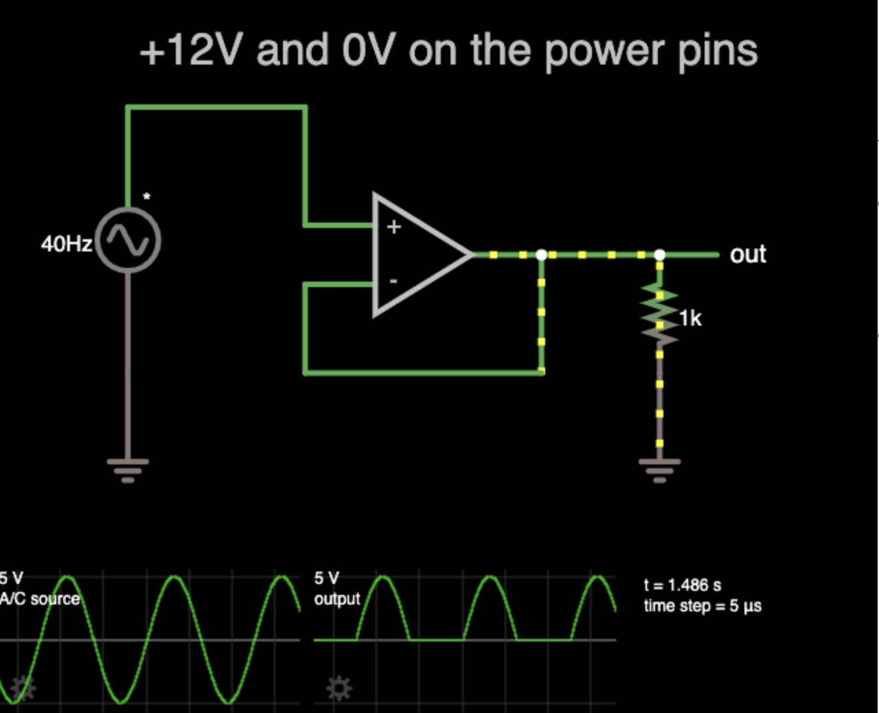
12V and 0V power-in, same 5Vpp input. Notice how the top of the waveform translates over fine, but the bottom half is cut off at the 0V line. Since we don’t have a negative supply, we can’t produce any voltage under 0V!
What if we could make the input signal ‘zero-cross’ at 6V instead of 0V? That way, we have 6V on each side of the waveform to work with instead of +12V in one direction. That is what biasing does.
Basically, all we’re doing is shifting the input wave up a little to make sure it stays within our valid voltage range. We can create a rudimentary bias voltage by simply using a voltage divider to split +12V in half. Two 10K resistors in series to ground will produce +6V in the middle when connected to +12V. Then, we simply connect that +6V to our audio signal source through a high-value resistor (1M does well), and boom, biased op-amp. Adding a couple support components like capacitors will help with stability and blocking DC.

12V & 0V supply, but this time with a 6V bias on the input signal. Notice how the output waveform is no longer clipped at the thick grey 0V line and has been shifted up. (Ignore the misleading graph scaling, the AC voltage is basically untouched. Notice how the voltage-per-division boxes are stretched differently.)
Blocking DC? Yep, we’re not done yet. DC voltages are extremely undesirable for audio circuits. Not only do DC voltages have the ability to accidentally bias components that aren’t expecting it, but they can burn out your speakers! DC voltages should be isolated and avoided at all costs. But wait, we just introduced DC voltage directly into our circuit via our bias circuit. How do we get rid of it and return to an unbiased, 0V zero-crossing AC signal? DC blocking capacitors. Capacitors will block DC and will only allow AC to pass through them. Therefore, in this example, adding a 10uF capacitor to the output of the op-amp will remove our DC bias and leave us with a perfectly buffered signal with no distortion.

Notice how the 10uF cap on the end shifts the AC voltage back down again. (Again, please ignore the misleading graph scaling. An RC filter was formed in this simulation, but is unrelated to the point, ignore the slight voltage drop.)
ALL OF THIS TO SAY…
Again, a bias is simply (your signal + a voltage). It will shift up your signal by the voltage you apply. Then, you can remove that shift up with a DC blocking cap. Phewph.
By the way, those simulator schematics above are kind of janky and were only required to make it work. Here is the actual circuit I used:

The way I would bias an unity-gain op-amp with a +12V power supply. R1-R3 divide 12V/2 to form 6V. R2 prevents R3 from sinking nearly any input signal power. C1 stabilizes the 6V from the voltage divider. C2 is a decoupling cap. C3 removes the DC offset (bias voltage).
If you are using a stereo audio stream, like I was, you will require two of those circuits. Fortunately, most op-amps come in dual or quad varieties. I used the LM833, but there are lots and lots of them out there. SA5532, TL072, LM358, just to name a few.
Breadboard Power Amp
Okay, finally, on to the rest of the prototype. For the most part, assembly was fairly straight forward. I just followed the datasheet provided by TI. They almost always include an example diagram that should get you up and running in no time.
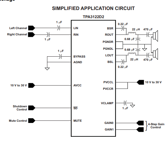
You can find the datasheet I used for the test amp here
To start, I always set the gain control to the lowest value, so I would ground pins 14 & 15. Pin 3, the MUTE pin, would also be grounded. Pin 2, the SHUTDOWN pin, is connected to 12V along with the AVCC and PVCCL/R pins.
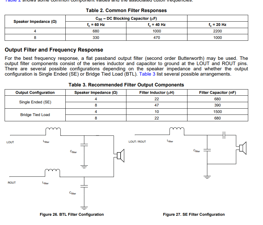
In the datasheet on page 12, you will also find a section on how to choose filter cap and inductor values. I am using a 4 ohm, single-ended configuration. A single-ended configuration means that the speaker is tied to one audio output line and ground. BTL, or “Bridge Tied Load,” means the speaker is connected between two output lines, usually for more power. For now, I’ll be using a single-ended configuration, but later, we’ll move to BTL. Anyways, according to the charts, I need a 22uH inductor and a 680nF cap for my filter.
Once the amp was set up, I hooked up my cheap little speakers and used their box as a temporary enclosure. Additionally, I set up a little Teensy board to sample the right channel of the audio input line. I create a circuit to do this correctly a bit later, but for now, I’m able to run a cool little FFT neopixel program on it to give me a mini light show to the music. I used a SN74LVC245 to translate the 3.3V signals from the Teensy to the 5V neopixels (WS2812), which were running off a 5V buck converter module. The Teensy was also powered by this buck converter.
Here’s a video of the first signs of life!
Some early pitfalls:
Class D amps, and well, anything analog really, hate breadboards. I don’t blame them, to be honest. Loose connections, stray capacitance everywhere, long wires, high-frequency components all smushed together. If you build an amp on a breadboard, be prepared for miserable performance. That being said, I love to always test my projects on breadboards first because it generally makes understanding the fundamentals a lot easier.
One issue I ran into was the Class D amp I used refusing to operate, instead, it gave off an odd-clicking noise. This is likely either the thermal protection or the short-circuit protection oscillating, turning the amp on and off since it couldn’t stabilize. To get around this issue, I would keep power-cycling the amp by unplugging and re-plugging the main 12V power wire. If I could catch the power cycle just right, the amp would fire up. Obviously, this is probably terrible for everything involved, but, you know… prototype.
I also discovered that +24V is absolutely the way to go when it comes to powering these amps. The quality is substantially better and you get much less distortion or dropping out when loud bass notes hit. I rewired the circuit a bit to run on +24V instead of +12V. I added in an adjustable linear regulator to generate +12V for the op-amp and it’s bias supply as +24V is far too high for op-amps. That linear regulator is hooked up to the potentiometer you see in the next video below.
Yeah, don’t be jealous of my sick reflex enclosure. Funny thing about that cardboard box though. In the video above, you’ll see me press the driver down into the box, snubbing some of the vibrations it generated. In person, it makes a pretty dramatic difference to the audio quality. Enclosures, vibration control, and predicting how the air will interact with itself are all parts of the amazing audio engineering puzzle that we sadly won’t be touching upon here, but are fascinating none the less.
Mixing
Alright, so that simple pre-amplifier “unity-gain op-amp” circuit that we spent so much time learning about has done it’s job admirably, but it’s time for an upgrade. For the final circuit, I’d like to have two audio inputs on the outside of the unit and one audio input on the inside of the unit. I’d like to be able to mix between them on the fly. The internal audio input will be useful if my client wants to add bluetooth audio support or have something inside of the enclosure to send audio to the amp. I’d also like a couple outputs – one external “mix out” line and one buffered audio line that the microcontroller can sample for the lights. The final mix will be sent to both the power amplifier and the two line level output lines.
This mixing circuit prototype actually went really, really well. I followed this guide and I really love the modular mindset. The performance is fantastic as well.
For the most part, I simply copied this schematic set verbatim and it worked out fine. I only changed a couple things:
- I got rid of the gain potentiometers, but kept the volume pots. I removed gain pots (R2A & R2B) and R3 & R6 and replaced that part of the circuit with a single 47K resistor. This gave the input amps unity gain, similar to our previous amp. I didn’t need those gain knobs as I felt 1-to-1 gain was fine and I’d prefer the PCB not be mega huge because of the interface panel.
- I ditched the biasing trick we learned in the previous section. Biasing all of those inputs correctly would have been a real pain, so I decided to move over to bi-polar power supplies at that point. Also, the op-amp topology was fairly different, as this approach relied on an inverting schema rather than non-inverting. Don’t have a bi-polar supply? I’ll show you how to make one for cheap!
Here’s how to make a +/-9V power supply using two 9V batteries and a bit of wire.
Pinch a bit of stranded wire in-between the positive and negative terminals of two 9V batteries. This is your “0V” point. The exposed + terminal is your +9V, the exposed – terminal is your -9V. Measuring between the two exposed terminals will give you about 18-19V.


You can also attempt to create a negative voltage generator using a 555, which does work, but they can’t really supply a whole lot of current and they tend to operate smack dab in the middle of the audible frequencies, so your signal is tainted with an annoying tone. I don’t recommend it, but you’re free to give it a try!
Oh, another annoying thing, you’re going to need some dual gang potentiometers. The most common types do not fit in a breadboard, so I had to assemble a little breakout board.


Source: Spehro Pefhany
After it was all hooked up, I had this!
Two mixing channels and a master volume controller on the final summing amp for this prototype. This circuit worked stunningly well, even on a breadboard. I was super impressed. The modular design of it makes it super easy to add as many channels as you want, too.
I used all LM833 op-amps soldered to little DIP adapter boards for this (though I was also testing an LM358 in the video).
Flux, good solder, and a chisel tip is all you need for sparkly clean SMD joints!
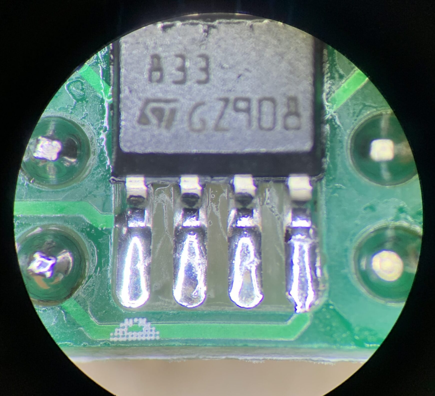
Eventually, I just ordered up a little +/-15V switch mode power supply board.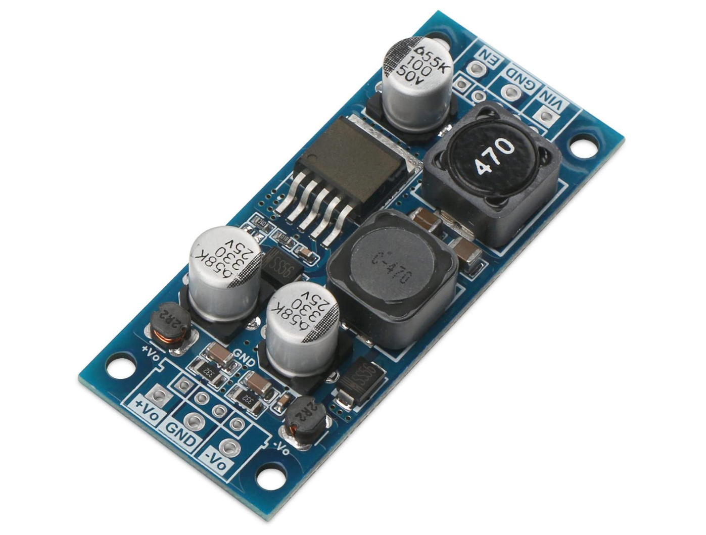
Bastards lasered off the part number on the main IC, making it “impossible” to look up the chip they used to design the circuit.
By “impossible,” I mean “minor annoyance.” I placed a little piece of kapton tape over the lasered part and firmly pressed it in place. Angle the light just right and hey, what do you know, it’s the XLSemi XL6019
This board works a treat and injects only a tiny amount of noise into the circuit, only really audible using headphones. I can’t really hear anything on full-sized speakers.
Makin’ the BIG BOARD
Cool. By now, I’ve become pretty confident with my ideas so far, so I figured I’d go big or go home. Yeah, enough of this 15W nonsense. Let’s bump it up by an order of magnitude. Let’s go with the raw, ear shredding fury of the
Hell. Yes. Check this bad boy out https://www.ti.com/store/ti/en/p/product/?p=TPA3156D2DAD
70W and channel, 140W total. Damn, I bet this amp is gonna be…
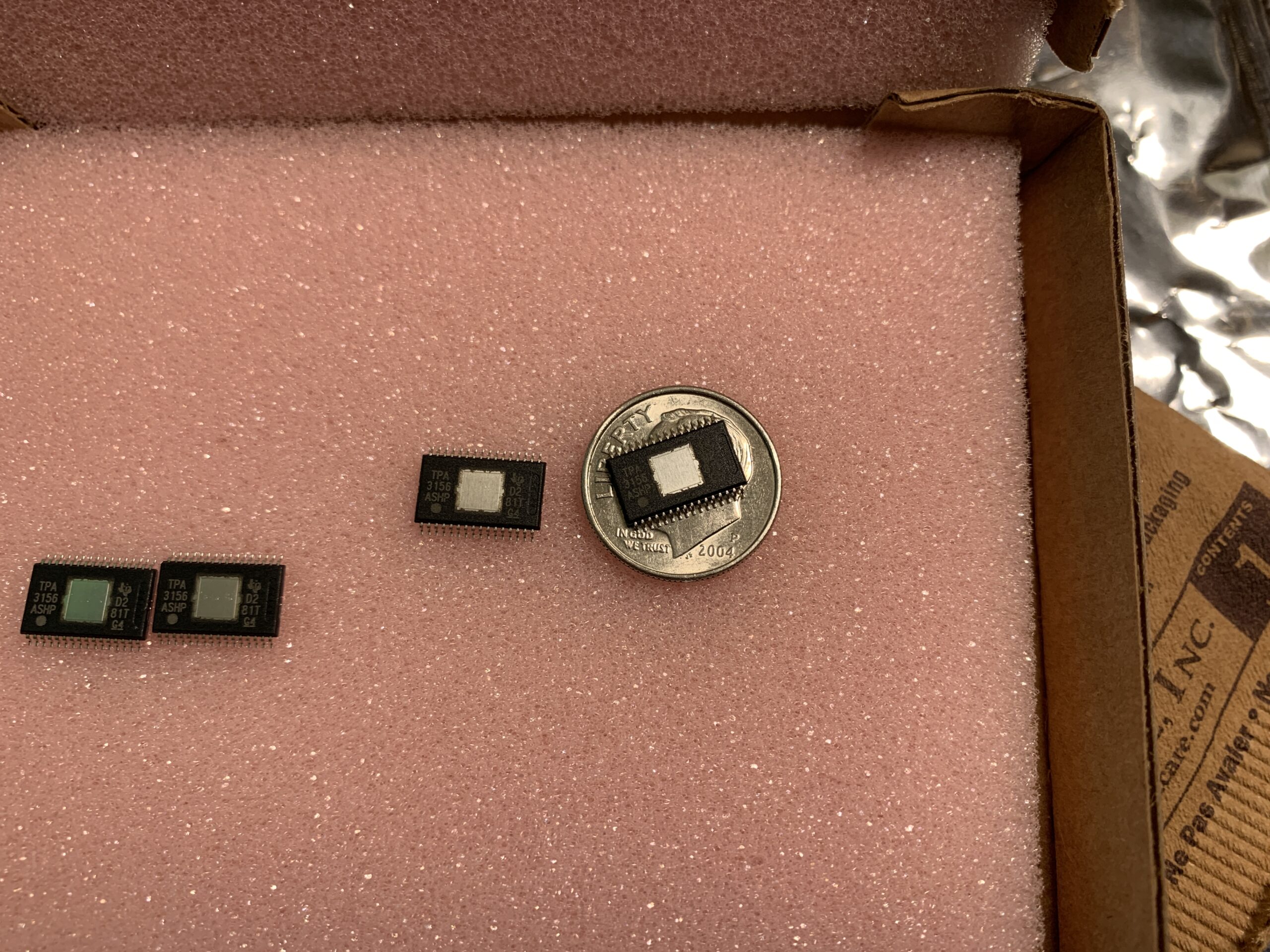
..ww…wha.. It’s so.. tiny… How the heck do you push 70W through those teeny-tiny legs? That’s more power than an old-school incandescent light bulb consumes.
Do you see why I think using Class D amps feels like you’re cheating the laws of physics? I understand the relationship between conductor length, resistance, and heat dissipation but STILL.
Alright, I’ll trust the TI engineers. In fact, I’m going to try and follow their reference verbatim. Honestly, with circuits that sink this much energy and rely on precision high-frequency switching, you really don’t want to free-hand this IC. Instead, look around to see if the IC manufacturer has created a demonstration board for their product. More often than not, their demo board web page will contain a whole bunch of great resources and in-depth examples that will help you create a high-performance design. You don’t have to buy the demo board of course, just reference it’s resources.
The TPA3156D2DAD does indeed have one of these demo boards. https://www.ti.com/tool/TPA3156D2EVM
More importantly, the demo board has it’s own datasheet with a TON of reference material and design examples. It even tells you the exact components they selected in the bill of materials!
Example schematics can also be found in the main datasheet, as well as a ton of helpful formulas and component value recommendations.
For the most part, the power-amp section of my design tries to follow the same design patterns as the development board. It may sound fun to cowboy the layout, but trust me, leave it to the brilliant engineers that designed this IC. They are going to know what’s best, so it’s really smart to use the resources they provide to create a design that mimics theirs. It’s not art theft, it’s a manufacturer recommendation… at least that’s what I told my Deviant Art followers.
My Design Considerations
- This power amp will be a “Master” device with the gain programmed to be 26 dB. Page 13 of the main datasheet tells you which resistor values to use for that. Breakout the SYNC pin in-case you want to add another slave amp in the future.
- My speakers will all be 8 ohms, therefore, the recommended output filter shown in the demo board datasheet example schematics (page 11) will work just fine.
- The example mute circuit shown in the demo board schematic is designed for a push-button. Modify it to work with a slide switch.
- Break-out the AM avoidance lines with with jumpers. You never know when you might have to change one of those settings in the future.
- I’ll use fork (spade) connectors to inter-connect everything since they’re fairly robust and easy to connect and disconnect.
- I’ll want some reverse current protection. A simple diode-fuse configuration should work just fine.
- My main power supply will be 24V. I’ll use a external switch mode module to generate +/-15V for the op-amps.
- I want three input mixing channels, all unity gain with volume control. There will be one unbuffered mixed output and a buffered mixed output for the MCU.
- For everything else, I will try to recreate the TI example circuit as best I can to optimize performance. Keep those traces thick!
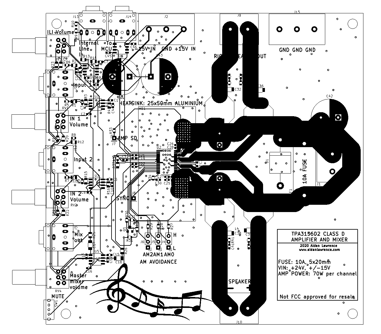
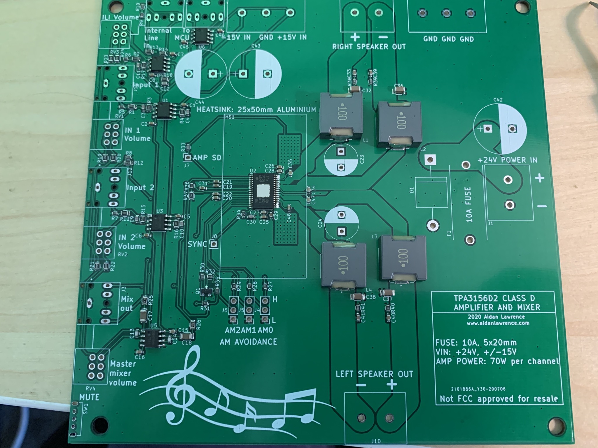
Here’s what I came up with for my amp and mixer schematic, click for a full view…

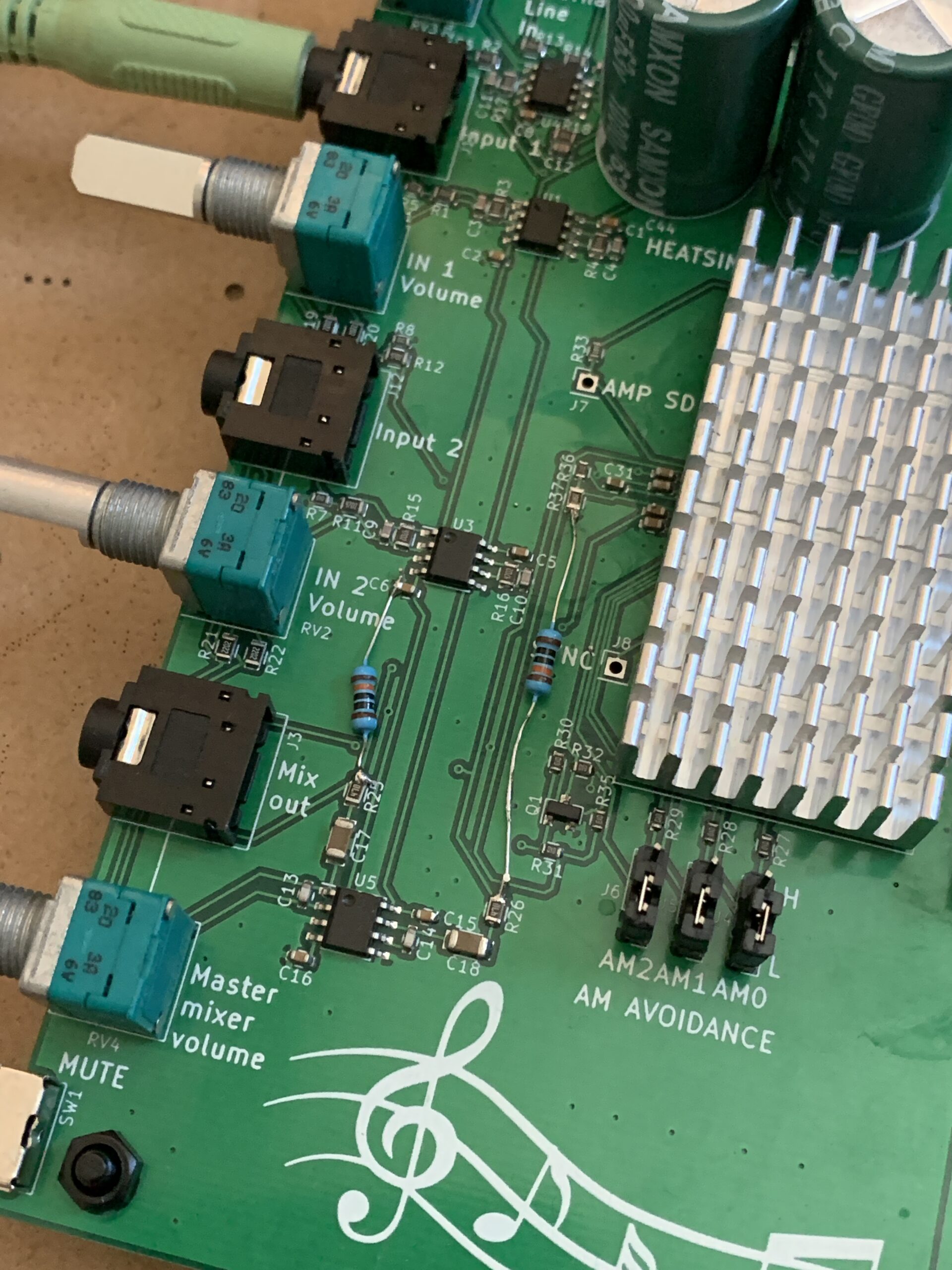
And the PCB without the ground pours. Notice how my topography tries to copy the TI demo board. I kept my power traces and output traces like Aku likes his Pizza. Plop down vias like they’re going out of style. This design worked almost perfectly. There is a sneaky little error with the C17 and C18 biasing the MCU op-amp, but I’ll go over how I fixed that soon.
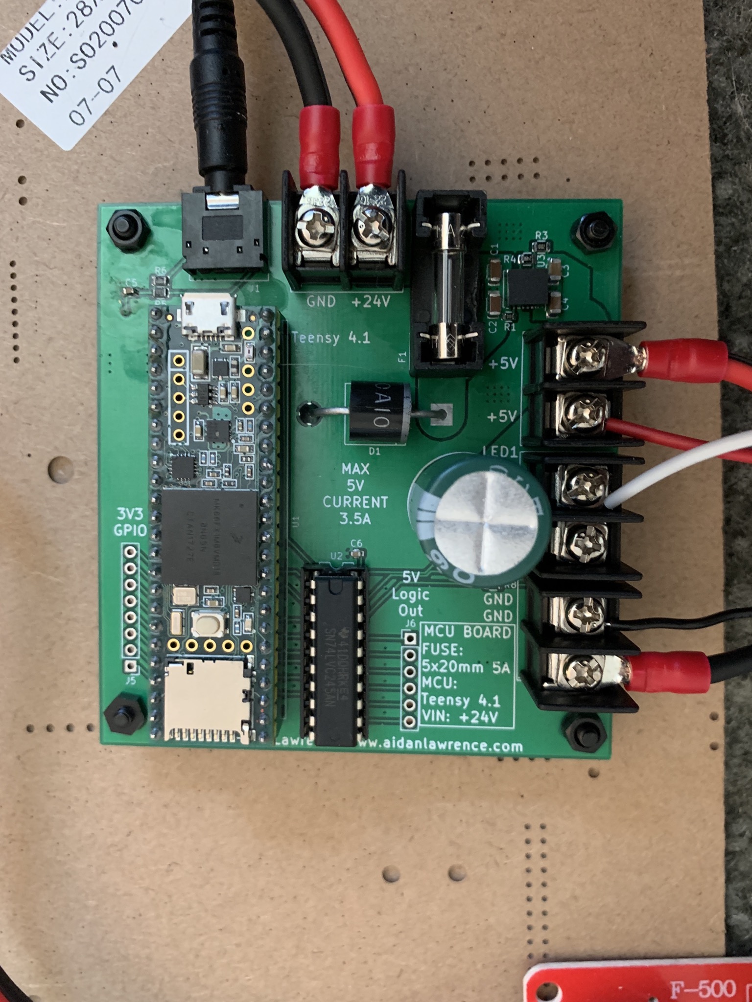
Here’s the microcontroller board in charge of sampling the audio mix…

I made sure this board was fused as well. I also found a great little DC-DC buck converter module capable of driving a 4 amp load in a 5x5mm footprint, which is incredible. The unit itself is INSANELY tiny. The box they shipped in seems comically over sized, three of them are in the top right of this image. Again, I simply followed the datasheet recommendations for the buck-converter components and board layout since it is a high-current, high-frequency device. She works a treat!

For everything else on the breakout board, I simply broke out a few pins on the Teensy for possible future use, as well as a few extra level-translated outputs, again, just in case. In retrospect, I probably should have gone with one of the smaller Teensys, but they are mostly pin-compatible with one another, so it’s not too big of a deal. It’s nice to have an upgrade-downgrade path if needed. I did have a minor oversight on this board as well, but I’ll go over how I fixed it in my troubleshooting section.
After sending my gerber files over to the fab, a couple weeks later, I had my PCBs and components! Let’s get building!
I have an SMD workflow. I greatly prefer it over through-hole. If you have a steady hand and good eyesight, it’s substantially faster than THT.

My “pick and place” machine
Board is populated and fresh out of the reflow oven!
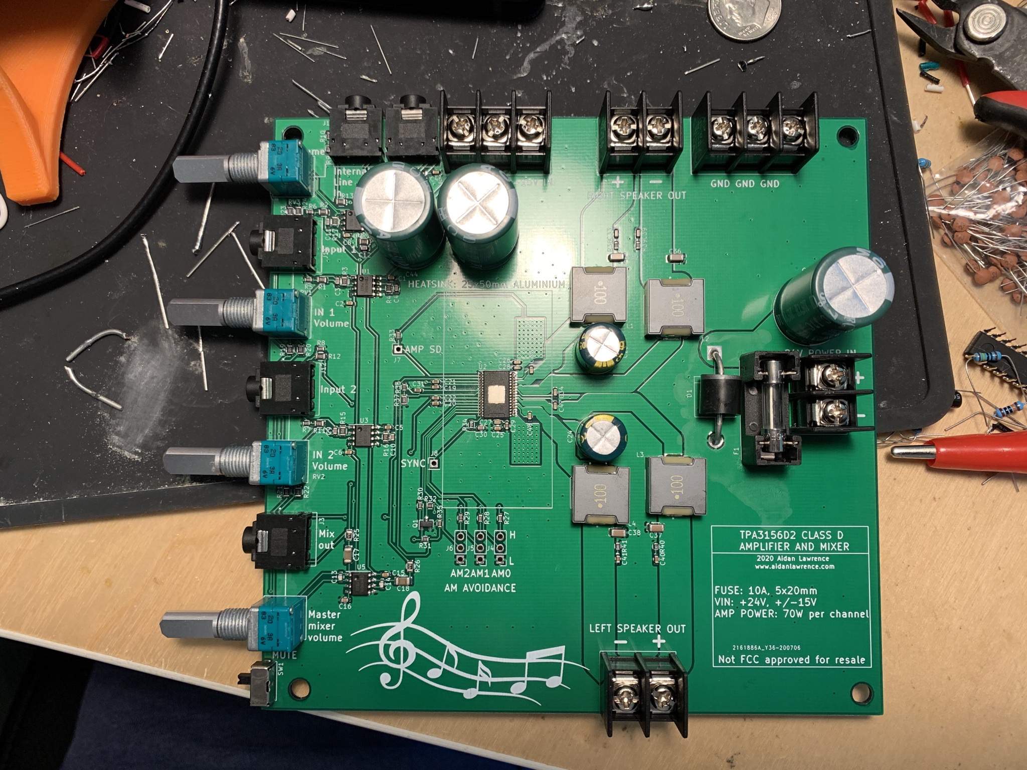
All done! How pretty… No shorts whatsoever, first reflow worked out great!
I managed to find some aluminum heatsinks on Amazon that fit the TI specification of 25×50 fairly well. I also picked up some cheap tubes of thermal glue – not thermal paste, mind you. I’d like the heatsink to remain in-place, so thermal glue fits the build better. I cleaned the heatsink off with a little acetone first, then applied a tiny amount of thermal glue to it and the power amp IC. It only took about a day to cure and it’s on there pretty good!
I also had the chance to try out a new solder paste that I just love. It worked SO well, it’s crazy. It smells like pine-sol and death, so it must be good.
SMD Reflow Tips
Time for Aidan’s QUICK SMD REFLOW AT HOME TIPS:
- Get a stencil. No seriously, get one. Trust me, it’s worth it.
- Use leaded solder if you can get it. Tin solder just SUCKS when you try to reflow it as it takes way higher temps.
- Use tubed solder-paste, rather than paste from a tub container. You usually get less paste in a tube for the money, but since it never dries out, you get substantially better performance.
- Use other PCBs around your main PCB when using the stencil to keep it in place and to have a flat surface to squeegee your paste on.
- Make sure your stencil is lined up as perfectly as possible. Try your best to get an even spread on the first pass, double checking that every component got covered. Then, quickly remove the stencil in one quick movement.
- A smudgy paste-job will make shorts much more frequent. If you can get the paste perfectly applied on each individual pad without any overlap, your board might come out with zero shorts on the first try.
- A steady hand and good eyesight really makes all the difference. If you’re dealing with a tricky part, hold your breath while placing it to stabilize yourself. If you can place the part with minimal smudging and good accuracy, you will get less or no shorts.
- Parts will move in-place by themselves when reflowing due to surface tension. You don’t have to place parts absolutely dead center, but good accuracy really reduces shorted or “tombstoned” parts. Just make sure the pads are all lined up.
- You don’t need a dedicated reflow oven, a toaster oven works just fine. With leaded solder, place your board in the oven and let it heat up to around 350°F (~175°C). You’ll see the components seat themselves. Wait a bit, turn off the oven, open the door. Let it cool naturally. I advise not using a toaster oven that you eat food out of.
- Examine your boards carefully for shorts using a microscope or magnifier. You can also hold your board up to a light source to see through it and spot shorts. Touch up shorts with an iron and lots of flux.
- A hot-air gun is extremely useful for parts that have phantom shorts or are not seated correctly. Highly recommended.
Audio Crossovers
Here’s something new that I wasn’t really aware of before this project: Audio Crossovers. What is a crossover? It’s a set of frequency filters that assign frequency bands to specific speakers. In a two-way crossover, the higher frequencies are sent to the tweeter while the lower frequencies are sent to the mid-range speaker. These protect your speakers from frequencies outside of their “frequency response,” which may distort or damage them if played. The frequency response of a speaker is simply the range of audio frequencies that the speaker can produce.
Basically, your amp is capable of producing the full audible spectrum of sound. The crossover is in charge of splitting that full spectrum up and delegating portions of it to each speaker. They’re simply arrangements of low-pass, high-pass, and band-pass filters, if you’re looking for google-able terms.
Ideally, you’d generally want to look for a set of speakers and a crossover circuit that would give you a “flat” frequency response. This generally involves quite a bit of engineering, equipment, and expertise to achieve. Since these speakers are not going to be for critical listening, some generic commercial crossovers will likely do just fine as you can find them for fairly cheap online.
How do you choose a crossover?
- How many types of speakers are you driving per channel? A tweeter and a midrange? You’ll need a “2-way” crossover. If you have a subwoofer, you will need a “3-way” crossover.
- What is the frequency response of your speakers? You can usually find this on their store page, box, or label. In my case, I have a tweeter and a midrange on each channel. The midrange’s FR is 600-10,000Hz and the tweeter’s FR is 3,200-20,000 Hz. I need a 2-way crossover that begins operating around 3,200 Hz, as that is where my tweeter starts responding. My crossover should split up the 0-20,000+Hz full spectrum from my amp into two sections, <3200’ish Hz for the midrange, >=3200 Hz for the tweeters.
- Make sure the crossover you select can handle your power requirements, otherwise, you might burn something out!
- You will require a crossover for each channel. Therefore, if you have a stereo setup, you will need two crossovers.
- Proper custom crossover design requires extensive testing and expertise. If you’re designing for critical listening, avoid pre-made crossovers. Custom crossovers will almost always sound better, but for all intents and purposes, commercial crossovers will work just fine.
Power Supplies
I went with a 24V industrial power supply since they are super easy to connect multiple devices to. The particular one I went with is a 350W Meanwell, which is absolutely overkill in terms of power required, but Meanwell makes really good power supplies, so I went with them rather than a cheaper, sketchier PSU vendor. You could also look for 12-24V DC power bricks too, but those are generally a bit harder to connect multiple devices to. Be careful when working with industrial power supplies though, as they really mean business with their output capabilities and require you to work with mains power. If you’re not comfortable working with mains, stick with a power adapter. If you work with an industrial power supply, you’re also probably going to want a power switch too!
First Tunes!
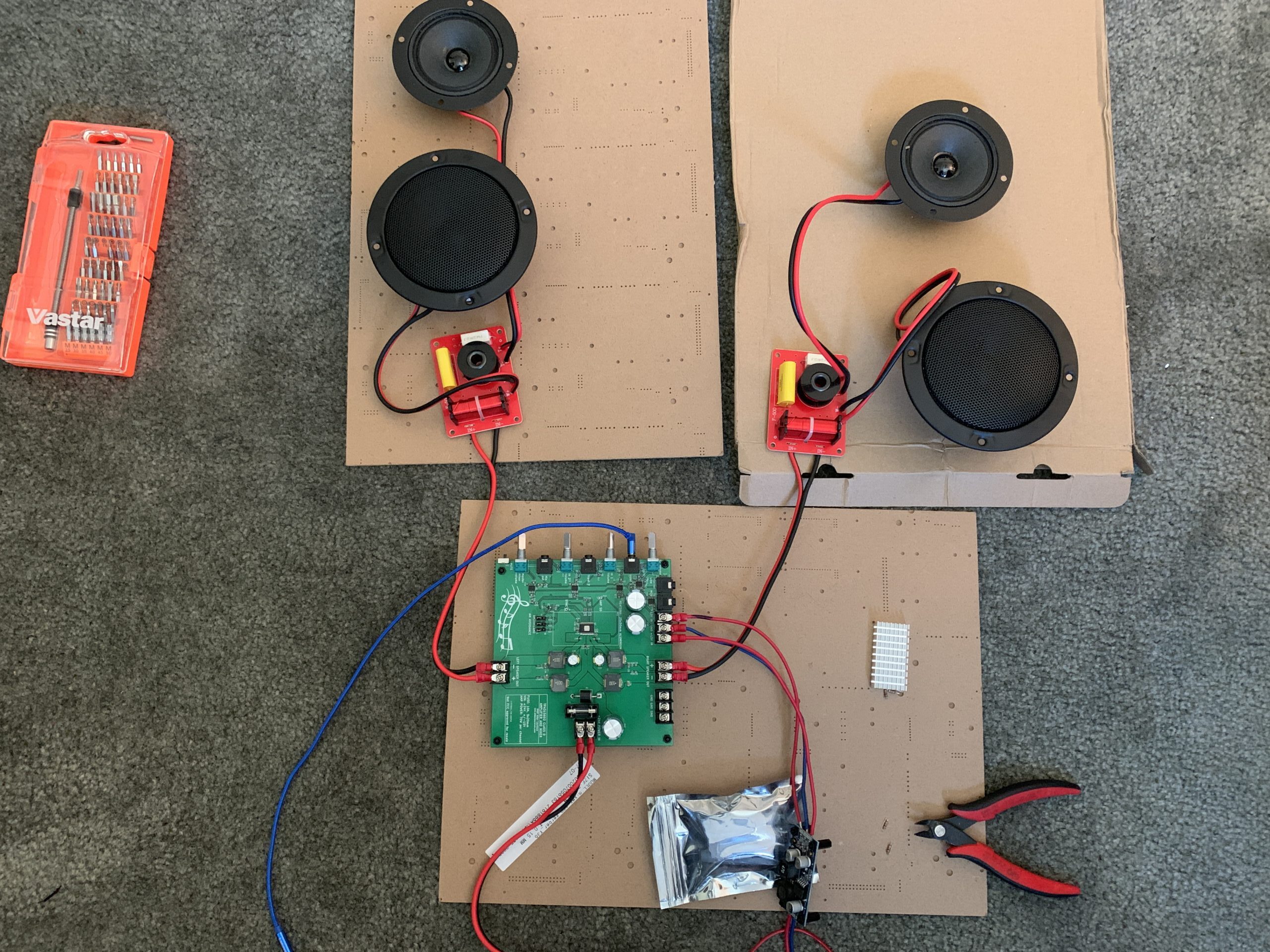
Everything is all hooked up for the first test! Make sure to test before applying your heatsink glue ;)
Finally, after a month or so of R&D, the moment has come. After testing the board with my current-limited bench power supply to make sure there weren’t any obvious shorts, I migrated over to my floor and began connecting all of the components together. the two red boards you see are my crossovers. The industrial power supply is just out of frame and is powering the amp board and the little blue +/-15V voltage generator. State of the art ESD protection was implemented by me trying not to rub my feet on the carpet too much and touching the chassis of the power supply before I poked anything else.
Yeah! Nothing feels better than a PCB that works on the first try! There was a tiny issue that I discovered a little bit later into testing, but it wasn’t anything I couldn’t fix with a couple resistors. Again, I’ll explain in the final troubleshooting section later.
Light Show!
The sounds work great, what about the sights? Time to put the light-show board to work. After a little bit of hooking-up, the light-show board was ready to go and was sampling audio from the mixer. This time, I hooked up about 90 addressable LEDs.
…but.. hm.. It “works,” but just.. not that well. Huh. The performance was inconsistent and the light circuit seemed to be picking up a ton of noise. After a bit of deliberation, I decided that the way I was sampling audio was really not ideal. It was at this point where I made a really dumb mistake – a particularly catchy tune was playing on the amp board, but I wanted to work on the light-show board. Okay, not an issue, just disconnect the power cables from the board and..

What ever happened here was fairly violent. Caps moved around from the hot air gun btw.
OH GOSH. Wow, sorry little buck converter module. What happened? Truthfully, I’m not too sure. I disconnected the positive 24V in lead first, so I didn’t have a “ungrounded” fault. I suspect that I may have caused some sort of fly-back malfunction while loosening the 24V cable. The module was running well within it’s spec, with the lights only drawing about 1.5A at max. Either way, that scared the hell out of me and necessitated me building another board since the traces were so damaged. Ughk, fine, whatever.
Troubleshooting
Other than the magical exploding DC/DC module, there were only a few small fixes I needed to make.
First up, I wanted to fix the sampling circuitry for the Teensy’s ADC audio input. The problem was that I was relying too much on resistors and relatively weak clamping diodes to protect me from audio sources that are a bit too hot. Also, the Teensy is unable to measure negative voltages, which is a real disadvantage for audio sampling. Not only would I not get the negative end of the audio waveform, but I’d also risk damaging the Teensy if an operator attached an extremely hot audio source. PJRC actually made a brief post on how to translate +/-5V “control-voltage” signals down to the 0-1.2V range, which would be perfect, since I could then use the Teensy’s high-accuracy internal voltage reference instead of the flakier 3.3V external reference. I changed a couple component values to adjust the input voltage range to around 3.5Vpp, but the result is fairly similar. The 27K resistor should also help protect against extremely hot inputs.

I doubled up this circuit, one for each channel. The two 1K resistors on the PCB will mix them down to a single channel. There is a LD1117 linear regulator on my new breakout to supply a stable 3.3V.

According to my simulator, this little circuit should have done the job nicely. But huh… I’m still getting really inconsistent performance with my LEDs. What gives? It’s like there is a ton of noise on this line or something. Wouldn’t it be funny if there was like a DC bias or something on the buffered mixer? Heh I’ll just go ahead and check with my multimeter just in ca…
OH MY GOD THERE IS +15V DC GOING INTO THE TEENSY WTF?
Thankfully, those 1K mixing resistors combined with the clamping diodes inside of the Teensy likely saved me, but I was still 50% over the current limit of 10mA. I think I got really lucky, my Teensy should have been toast. What the hell is supplying 15V to the MCU buffer op-amp?
As it turns out, it was C17 and C18. They shouldn’t have ever been at that voltage, but it seems as though the initial power-up, or perhaps a stray voltage source, tosses a 15+V pulse into the system, which charged those caps up. Since those caps aren’t being sampled by anything that sinks any significant direct current, they never discharge, and the MCU buffer op-amp is registering them as a DC offset and biasing itself to compensate. Super strange issue that I would have never caught beforehand. Thanks for the tip, Natalie! The result is a permanent +15V on the output of the MCU buffer op-amp, instead of a purely AC audio signal. A couple bodged 100K resistors to ground quickly fixed that issue. I updated my schematic to reflect those resistors.
No shame in a little bodge. It’s better than damaged components.
After those two fixes, BOOM! Lights worked GREAT! Here’s a demonstration of them running in “VU Meter” mode.
Amazing! It looks so cool! That little DC/DC module is seriously impressive. It’s about the size of my pinky finger nail and is supplying about 1.5-2A of power without a sweat.
The speakers themselves sound amazing in person. They come across as tinny on my phone’s microphone, but in real life, they’re fairly full and impressive sounding, even without a subwoofer or enclosure. Totally loud enough to shake my fillings. Wait, I don’t have any fillings. You get the idea.
What’s Next?
Well, this only happens to be one half of the entire project. The enclosure is being handled by the person that commissioned this system, so I’ll leave that part to them. At this point, I’m interested in creating some more amazing amplifier projects. This stuff is endlessly fascinating. Who knew so much went into “make small noise more louder.”
If I had to re-design this board, I would make the following changes:
- Find a way to make the mixer-amp board a bit smaller. Maybe even separate the mixer and amp board to make it easier to expand the mixer input panel a bit and not worry about the size of the amp board.
- Find a smaller sized 1000uF 24V+ cap. The ones I got work fine but are a little big.
- Integrate my new ADC breakout circuit on the light-show board.
- Create my own custom power supply solution for the +/-15V generator.
Helpful Resources
Here are some of the places I searched around for helpful info and tips:
https://www.circuitlib.com/index.php/tutorials/product/39-how-to-build-an-audio-mixer
https://electronics.stackexchange.com/questions/153911/single-supply-op-amp-audio-amplifier
https://dorkbotpdx.org/blog/paul/control_voltage_cv_to_analog_input_pin/
https://sound-au.com/p-list.htm
And yet again, my good friend Natalie who was always happy to give me extremely helpful answers no matter how trivial they seemed. You rock.