May 19, 2018
There is a new and greatly improved version of the Mega Blaster out now! Check it out here!
MegaBlaster
My completed Hardware Sega Genesis Video Game Music Player


I couldn’t just leave the Sega Genesis Hardware Music Player project as a perfboard prototype. I know that I said in my last entry that I would likely not make a PCB for this project… but… that was loser talk. Since then, I’ve gotten pretty good at creating schematics, PCBs, and all the pretty things that go into a project like this, so I figured I’d put my new skills to the test and give the Genesis player the send-off it deserves. I’ve also given this project an official name:
The MegaBlaster
Cheesy? A little, but so were the 90’s, so I think it’s perfect. The board was designed with a blue Outrun theme with wavy, palm-tree board art along the front and back sides of the player. I think that it looks pretty nifty!
Not only have the aesthetics of the project changed drastically, but so has the circuitry! The Megablaster features a new STM32-based microcontroller board, a brand new mixer, a preamp circuit, and a significantly improved power amplifier based on the class-D TPA3122D2.
Prototyping with a new microcontroller
So here’s the thing. I LOVE the Teensy-series of boards. They’re incredibly fast, jam-packed with I/O pins, and have ample RAM/ROM storage. Their only downside? They’re REALLY expensive. As of right now, the Teensy 3.6 goes for about $40 (shipping included). For what you’re getting, I’d say it’s worth it, but my Teensy costs were really adding up and I don’t think it was really fair for people that wanted to create my projects to have to shell out so much money just for the microcontroller. I had to find an alternative. That’s where the STM32-based “bluepill” board comes it. You can find these boards for less than $2 on places like Aliexpress and Ebay. The official name for the microcontroller is the STM32F103C8T6, and it is an ARM Cortex-M3 core running at 72 MHz with 20K of RAM and 64K of flash. No where near the raw horsepower of the Teensy’s Freescale 180 MHz ARM Cortex-M4 with 1M Flash and 256K RAM, but the STM32 has just enough horsepower for this project with a little clever engineering. Further still, the I/O on the STM32 board, while still relatively ample, was only just enough to get the project to work.
Now, I’ve made a VGM player based on the STM32 bluepill before. On that player, I was driving a YM2151 FM-only synthesizer and that was pretty much it. I didn’t have to worry about an extra PSG chip or PCM samples, so the on-board 20K of ram was more than enough to get this player to run at full speed.
For the Sega Genesis, though, not only would I have to drive the YM2612’s FM channels, but I would also have to drive the separate SN76489AN PSG chip, AND I would have to account for PCM samples. For those who don’t know, PCM (Pulse Code Modulation) samples are basically ‘recorded samples’ of real-life sounds. They are not mathematically synthesized like the FM waveforms, but are instead raw prerecorded audio data chunks that are played back on the YM2612’s channel-6 Digital-to-Analog Converter (DAC). If you have ever played back a .wav music file on your computer, that is basically a PCM waveform (get it, .wav… waveform… eh?) file that is just filled with a bunch of values that represent voltages that the DAC must output to your speakers. On the YM2612, PCM samples are usually used for drum kit sounds or crude voices recordings, such as the iconic SEEEGGAAAA chant at the beginning of Sonic the Hedgehog. They’re great for adding a little bit of texture to the usually smooth-sounding FM waveforms. Only problem? They require a TON of RAM to store. So much so, that the same SEGA chant mentioned above takes up 1/8 of the cartridge space for Sonic the Hedgehog. Storing arbitrarily long PCM samples on 20K of RAM on my STM32 board was simply not going to work out, so I needed a work-around.
External SPI RAM to the rescue
Fortunately for me, easy-to-use external RAM chips do exist and they’re dirt cheap. I chose a Microchip 23LC1024 SPI RAM module for this project, instantly adding 1M of RAM to my system. Since this is external RAM, I was a little concerned that it simply wouldn’t be fast enough to keep up with the VGM stream. Thankfully, SPI RAM is lightning-fast when driven correctly.
I wrote my own simple driver for this SPI RAM and used exclusively for PCM sample storage. When ever my player parses a PCM data block, it quickly stashes it in the external RAM (sometimes heard as a brief buzz-buzz-beep-beep at the beginning of some tracks), and any time that sample is played, it simply pulls the data from external RAM. To keep I/O speeds high, I used a dedicated SPI bus just for the RAM chip set to the fastest clock-division setting I had access to and kept the SD card on its own SPI bus. This used up more precious I/O, but the speed was totally worth it. Handling and storing PCM samples correctly is probably one of the biggest challenges when working YM2612s, so I’m glad this solution worked out so well. 1M of RAM is all we could ever need, right?
Uh Oh, I/O
Another challenge to this project was juggling I/O. When you get used to the cushy I/O availability of the Teensy, it’s hard to adjust to something a little more conservative like the STM32 boards. I had to drive two sound chips, both of which used parallel buses and had lots of peripheral option lines (Chip selects, A0, A1, RD, WR, IC, and so on), an SPI interface for the SD card, a UART interface for the CH340G, an SPI interface for the RAM chip, an I2C interface for two LTC6904 clock generators, an OLED display, and 4 control buttons. Oh man. There just so happened to be a perfect amount of GPIO pins for me to completed this project, but it did take a little engineering on my part to get everything to fit.

The Megablaster prototype on breadboards
First off, the obvious GPIO savers. I should have been doing this from the start, but the YM2612 and SN76489AN can share an 8-bit parallel data bus. That’s what the chip select pins are for. Previous versions of the Genesis player had two dedicated parallel buses simply because there was enough I/O and I wanted to add LEDs to each bus to visualize the data heading to each chip. While the LEDs were super cool, for the sake of pin availability and board space, I removed the LEDs and consolidated the buses.
Next, saving GPIO on the clock generators. First off, you may be thinking, “Aidan, why not just use dedicated crystals for the clock generators?” to which I would say, “You could, but good luck finding a 7670453 Hz crystal, dynamically adjusting for PAL/NTSC recordings, and stuffing more crystal driver hardware on an already crowded board.” I’ve grown really fond of the LTC6903s since they’re so easy to use, tiny, and can generate just about any frequency I want on the fly. Only problem? LTC6903’s are SPI devices, and therefore require quite a bit of I/O, especially if you want more than one of them. That’s where the LTC6904s come in. They are functionally identical to the LTC6903s, but are I2C based instead of SPI. Since I required two LTC6904s, I was worried that I would run into I2C bus conflicts. Fortunately, you can chose from two I2C addresses by simply pulling up or down the SEN/ADR line of the LTC6904. Perfect! Switching to the LTC6904s saved on two GPIO pins. Also, since the OLED display was also I2C, it wouldn’t require any extra GPIO.
By now, I had enough GPIO to run the player itself, but was one pin short of my usual button interface of LOOP, PREVIOUS, RANDOM, NEXT, and SHUFFLE. I simply consolidated the LOOP/SHUFFLE into one button and renamed it “playmode.” You can also hold the playmode button and tap the random button to turn off the noisy OLED display. Perfect! I had everything I needed!
New mixer, pre-amp, and power-amp
All previous iterations of the Genesis pretty much had the same mixing and amplification schemes based two LM386 class-AB amplifiers. The problem was that the audio signals weren’t mixed together all that well with the PSG sometimes cranking it up to 11 and overshadowing the YM2612. This new mixer based on the Genesis’ actual schematics aims to fix that problem and seems to be working nicely. One of the biggest additions to this circuit is the pre-amp. Before, I would simply feed the mixed audio channels directly into the LM386 power-amps without any pre-amplification. This resulted in an “OK, but a bit muddy” sound profile. Detail was lost using this method and stressing the sound chips to push through the impedance of a power amplifier wasn’t the way to go all things considered. To remedy this, I added in a TL064 OP-amp to serve as a stereo pre-amplifier whose output would eventually end up at a dedicated power amplifier. Adding a proper pre-amp made a night-and-day difference in sound quality in my opinion. Sounds are clean, sharp, well-balanced, and sound just the way they were intended to be heard. Awesome!
Finally, the new power-amplifier circuit was added in. Similar to my previous YM2151 Arcade Classic board, I chose the 15-watt TPA3122D2 class-D amplifier for its ease-of-use, output power, and best of all, stereo support! No more dual LM386’s with their quadrillion capacitors all over the place. Best of all, this beast of a power amplifier can crank-it-out and sounds crystal clear. The design right now has the power option set to the lowest setting and it can still get surprisingly loud. The TPA3122D2 has become my go-to power amp.
Finally, a feature that has been missing on all of my previous players, volume control! This is handled by a logarithmic 10K, dual-ganged potentiometer on the output of the power-amp. Some electrical engineers might read this and think, “Why place the pot on the output of the amp instead of the input?” Answer: Placing the potentiometer on the input of the power amp destroys the sound quality. Why? I’m actually not quite sure. If I was to hamper a guess, I would think that the OP-amp simply can’t handle the voltage drop that the potentiometer places on the circuit, collapsing the output voltage as a whole. Either way, placing the pot on the output seems to work perfectly fine and the sound quality is great. Just don’t expect to drive huge, low-impedance speakers with this thing lest you wish to burn out the potentiometer.
Super-Sonic GPIO
In order for a VGM player to operate at the correct speed, it needs to perform I/O operations quickly. Since the STM32 board I’m using is Arduino-compatible, it may be tempting to use the DigitalWrite function for everything. For non-speed-critical operations, this is totally fine, but for things like data buses and RAM read-writes, you have to push your data directly to the STM32’s I/O registers. This is actually not too hard for little things since it’s similar to just writing to the PORTx registers on an AVR chip, but I did run into an issue where there wasn’t an easily available set of 8-pins on a single register that I could use for the parallel data bus. All of the STM32’s ports were interrupted with other communication ports like UART, SPI, and I2C that I needed access to, therefore, I needed a way to arbitrarily write data quickly to an 8-bit data bus spread across several registers. I came up with this monstrosity.
unsigned char data;
((data >> 0)&1) == HIGH ? GPIOB->regs->ODR |= 1 << 8 : GPIOB->regs->ODR &= ~(1 << 8); //PB8
((data >> 1)&1) == HIGH ? GPIOB->regs->ODR |= 1 << 9 : GPIOB->regs->ODR &= ~(1 << 9); //PB9
((data >> 2)&1) == HIGH ? GPIOC->regs->ODR |= 1 << 13 : GPIOC->regs->ODR &= ~(1 << 13); //PC13
((data >> 3)&1) == HIGH ? GPIOC->regs->ODR |= 1 << 14 : GPIOC->regs->ODR &= ~(1 << 14); //PC14
((data >> 4)&1) == HIGH ? GPIOC->regs->ODR |= 1 << 15 : GPIOC->regs->ODR &= ~(1 << 15); //PC15
((data >> 5)&1) == HIGH ? GPIOA->regs->ODR |= 1 << 0 : GPIOA->regs->ODR &= ~(1 << 0); //PA0
((data >> 6)&1) == HIGH ? GPIOA->regs->ODR |= 1 << 1 : GPIOA->regs->ODR &= ~(1 << 1); //PA1
((data >> 7)&1) == HIGH ? GPIOA->regs->ODR |= 1 << 2 : GPIOA->regs->ODR &= ~(1 << 2); //PA2
Hey, don’t judge. It’s fast as all get-out and works… It’s just.. ugly.. is all. But there you go, a speedy 8-bit data bus spread across several different registers.
Schematics and Source Material
As always, I provide these projects to you at absolutely no charge. Everything about this project is free and open-sourced. Feel free to build your own or remix my project and make your own version!
Here is the schematic:
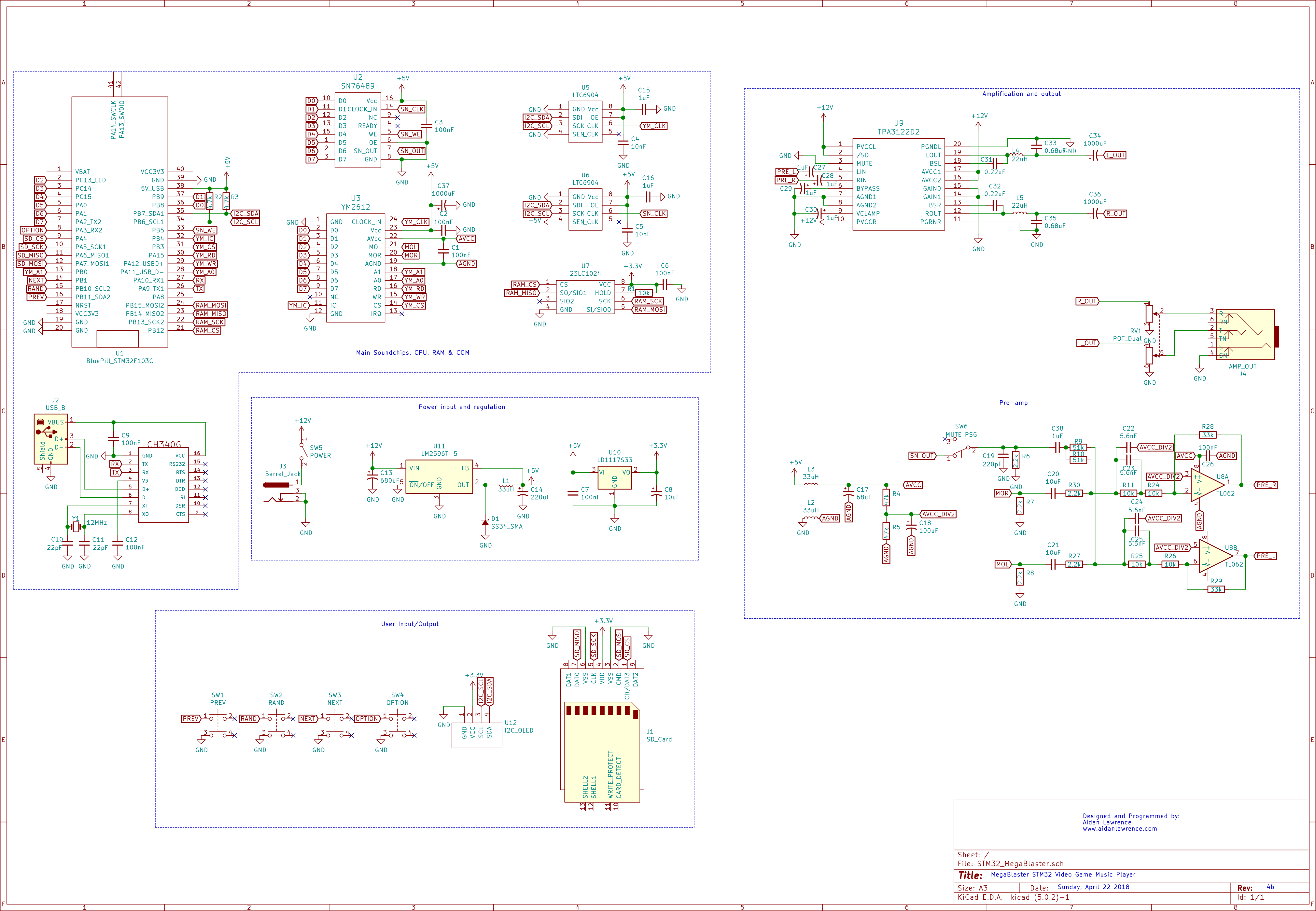
Click this image to see a PDF version
Here is the Bill of Materials (BOM).
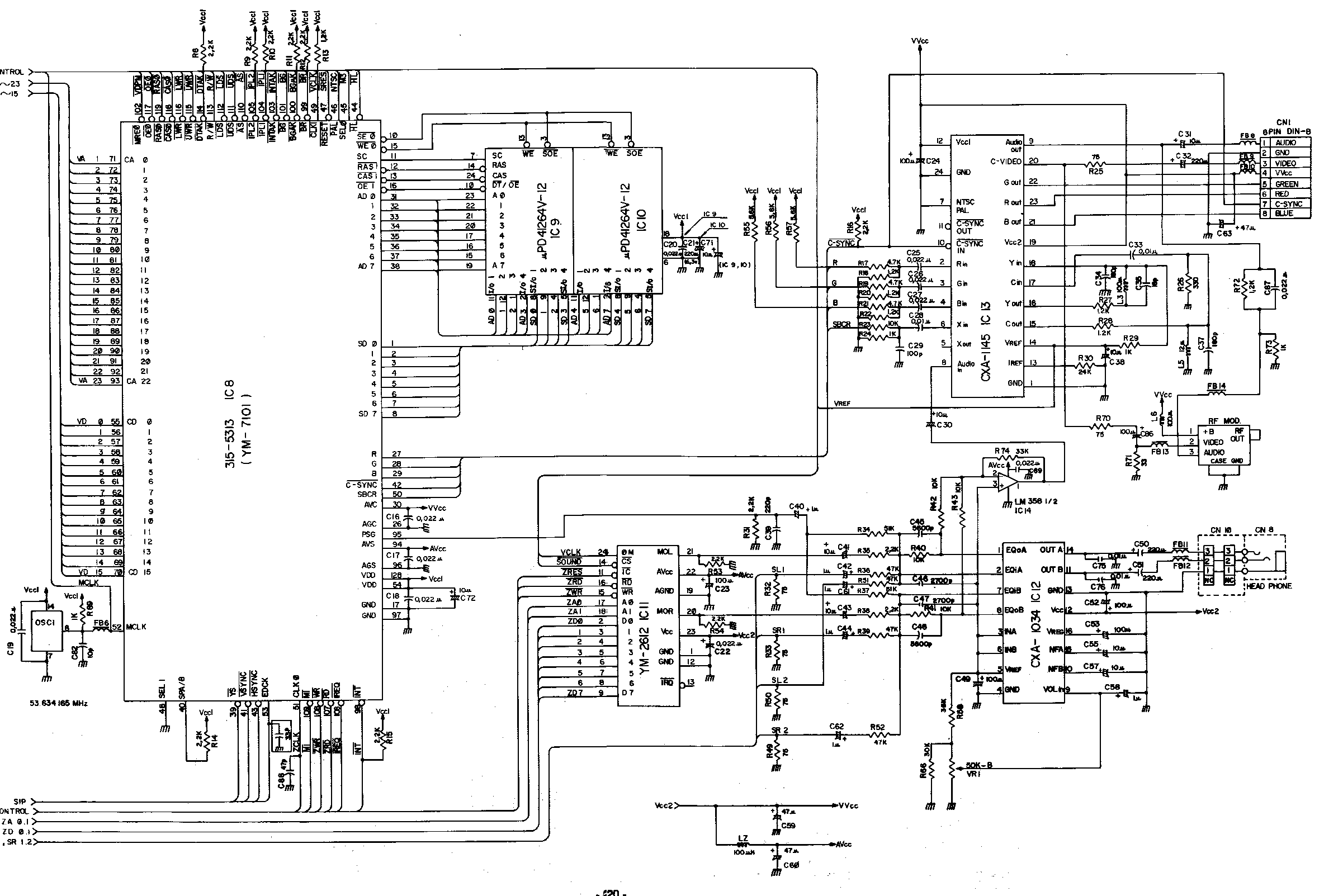
Also, if you’re reading this, you might be interested in the Datasheet for the YM2612… Well…
Yeah I would be to, that thing don’t exist. BUT what does exist is a Japanese copy of the YM3438 – the CMOS equivalent to the YM2612. If you can’t read Japanese, this might be tough to parse through, but I advise you to give it a look and use Google translate’s image translation feature. This datasheet is the closest thing we have to a proper YM2612 application manual.
Click here to view the YM3438 application manual data sheet.
Click Here to View the MegaBlaster Source Material On Github
Check out this awesome interactive assembly guide!
Thank you very much for the support and well-wishes along the journey of this project. I appreciate it very much. If you’d like to see a playlist of the progress from my first ever Sega VGM player to now, check this out!
Such an amazing project!
Very cool project! I looked at your GPIO code and thought of a suggestion to set all your pins with a few less instructions. Although it doesn’t sound like you need such optimization, maybe the shorter code looks nicer ;-) , or is at least hopefully a useful tip for future use.
Pasting a link since I’m not sure if this comment box will format code properly:
https://gist.github.com/thehans/7ac8a5f5030407dd94cee5c81dbafc15
I haven’t tested the code so there may be mistakes in there, but the idea is just to mask out the contiguous sets of pins, and comparing with the current register data via XOR. If a bit differs, then the appropriate bits get set on the right side of the operation. Then the full result is written to the register by XOR assignment of the register with those bits which differed.
Cheers!
Oops, I just realized that the bits are on different GPIOA/B/C, which I didn’t see in my previous comment. Still I think each of those could be set with a single statement, so 3 assignments instead of 8.
Hey Aidan, incredible project!! This is truly a gem. A huge thank-you for all your hard work on this!
I’m ordering PCBs to build it and was curious to know what the difference is between the v2 and v2b (“special”) revisions in your gerber files?
Cheers,
R
Thank you very much! Glad you enjoy the project! I believe the V2 special board has mounting holes drilled in it while the V2 board does not.
Btw, there have been a few end-of-life notices for parts on this board, so make sure to double check that you can source parts (or parts that fit) before you order everything! You can always edit the board, too!