August 5, 2017
Hardware Sega Genesis Video Game Music Player
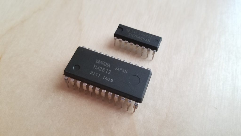
A hardware Sega Genesis / Megadrive VGM player that uses the real YM2612 FM synthesizer and SN76489 PSG chips!
My Biggest Electronics Project Yet
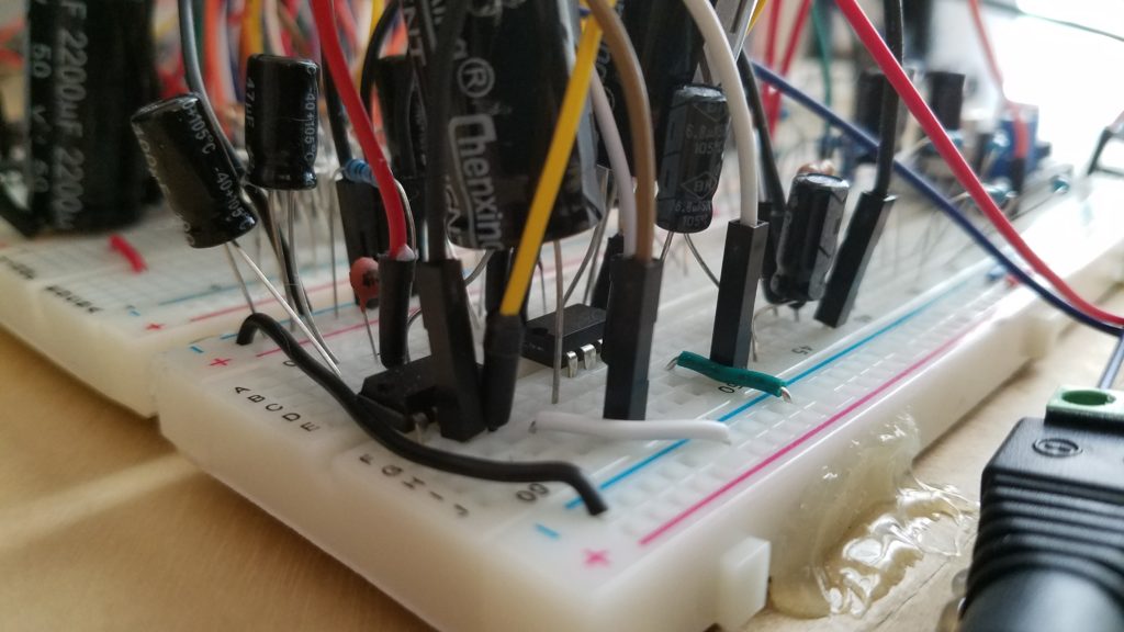
It's safe to say that I'm pretty proud of this one.
I thought that the Sega Genesis always had an awesome sound when it came to its music. The Genesis' smooth blend of rich synthy tones, gritty guitars, and kick-ass bass drew me towards investigating the sound hardware behind the console. Turns out, the Genesis houses a real monster of a sound chip inside: The YM2612 Frequency Modulated Synthesizer, AKA OPN2 (FM Operator type N 2). Not only that, but the Genesis also houses an SN76489 Programmable Sound Generator (PSG) that worked in tandem with the YM2612 to add even more sound channels to the mix. After a bit of light research, I jumped on Ebay and impulse-bought a few sets of both the YM2612 and the SN76489, not knowing the arduous electronics journey that lay ahead of me. Unfortunately, the YM2612 has essentially been lost to time. There exists no official documentation on this chip - even contacting Yamaha Semiconductor directly bore no fruit as they have discarded all documents related to the OPN line of chips. My only resources were a brief Wikipedia article and a recreation of the infamous leaked SEGA2.DOC. For everything else, I had to scrounge around the deepest corners of the Internet for little scraps of information here and there, or figure it out on my own. ...The latter happened more often then the former.
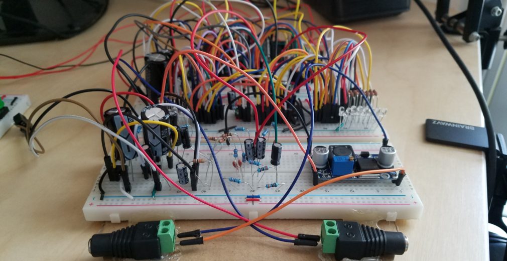
The Project in Action
A Year-Long Struggle Condensed Down to a Few Paragraphs
Information on the Two Sound Chips
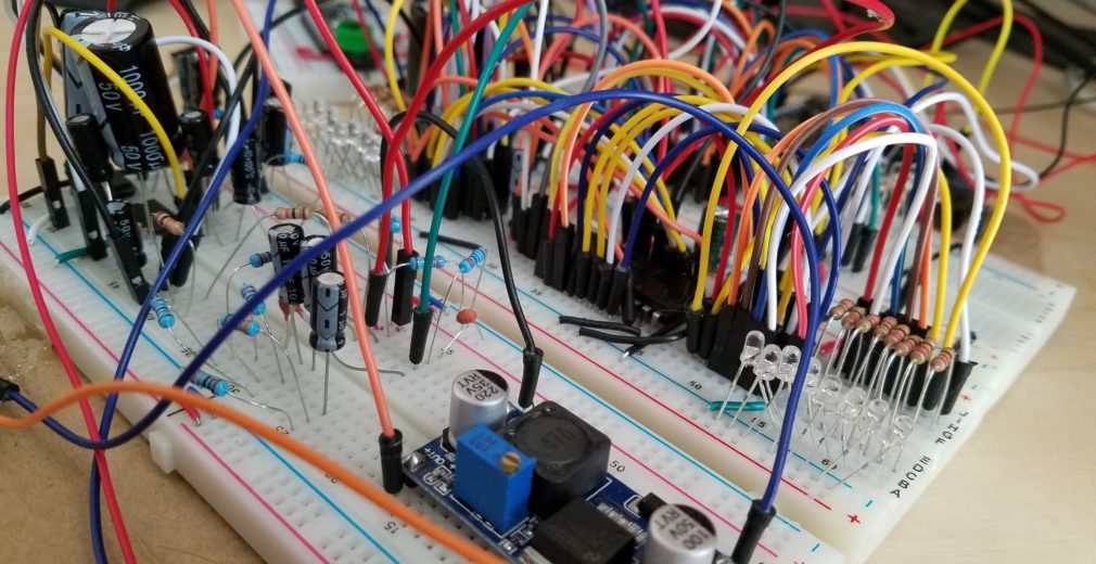
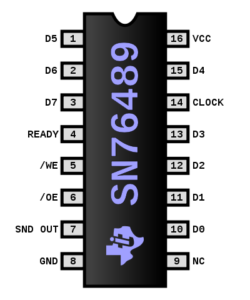
First, let's start with the simplest of the two chips, the SN76489 PSG. It's full name is the SN76489 Complex Sound Generator, but contrary to the name, it's actually a fairly simple chip in respects to the YM2612. The PSG is capable of producing three square-wave channels and one random noise channel (usually used for drum sounds). It was originally found in the 8-bit Sega Master System, as well as a bunch of other old home PC's (BBC Micro) and video game systems. The PSG was included with the Sega Genesis as a backwards compatibility feature to allow the Genesis to play Master System games; however, the PSG could still be accessed while playing Genesis software. Clever programmers often included PSG functionality in their sound drivers so music composers could have a tiny bit more umph to their songs, simple as the PSG may have been. You can see the data flowing to the PSG in my project by looking at the flashing red LED's. There exists a super simple Arduino Example that will show you how to operate a single channel of the PSG here.
The SN76489 PSG requires a 3579545Hz (3.58 MHz) clock signal in order to function properly. 3.579545 MHz crystals do still exist, but they may be a little tricky to find. An easier solution would be to use a programmable oscillator such as the LTC6903. I'll discuss clocking in more detail later.
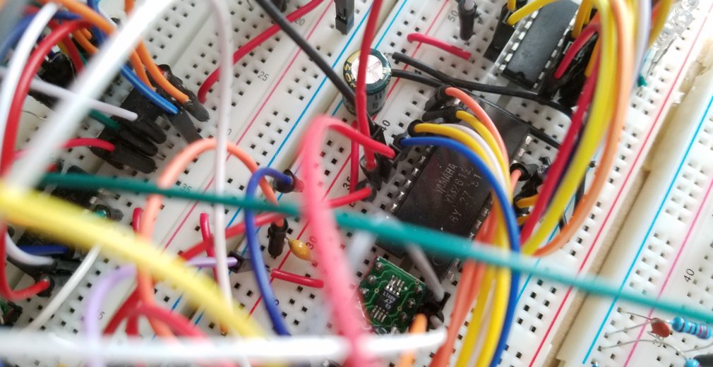
The Big Bad YM2612
The Yamaha YM2612 is the sound of the Sega Genesis. It's a 6-channel Frequency Modulated (FM) synthesizer with a built-in Digital to Analog Converter (DAC). The YM2612 is a cut-down version of the 16-channel YM2608 chip, lacking features such as the SSG, ADPCM, and Rhythm sound sources. In place of the missing ADPCM feature, the YM2612 is capable of reproducing digital audio samples by converting the sixth FM channel into a PCM (Pulse Code Modulation) channel. Even though the YM2612 was a relatively low-end sound chip, in the right hands, it could produce some ridiculously good sounding music.
Very little official information exists for the YM2612. It has been officially end-of-life since the late 90's, and according to Yamaha Semiconductor, all of the official datasheets and application manuals for the OPN family of chips have been purged... which is sad :(...
This means that developing new projects that involve the YM2612 are going to be a massive struggle-fest. There exists a recreation of a leaked Sega document known as SEGA2.DOC that outlines the registers of the YM2612 and provides example pseudocode to create a piano tone. This piano tone is actually fairly easy to recreate using just an Arduino as shown by this project on Github. This project serves as an excellent starting point just to get some sound out of the YM2612 and to get an understanding of how the chip actually accepts data.
Keep in mind that this is about as far as you're going to get with just an Arduino. In order to quickly control both the YM2612 and the PSG to play video game music, you will need a chip with a LOT more horsepower. You will also need to create an amplifier circuit as the output of the YM2612 is very, very quiet. Directly driving speakers or headphones from the MOR/MOL outputs may work for quick prototypes, but will quickly heat-up the YM2612 and may damage the chip. For those out there wondering, the output impedance of the YM2612 is about 1k Ω, same with the PSG. The difference is that the YM2612 is about -27 dB below the PSG's output level, so clever mixing techniques needs to be applied. You can view my amp/mixing circuitry in the schematic found here.
The YM2612 requires a 7.670442MHz clock signal. Crystals at this exact speed are next to impossible to find, though rare 7.68 MHz crystals do exist and would probably work for this project. As with the PSG, it's probably easier to just get a programmable oscillator such as the LTC6903.
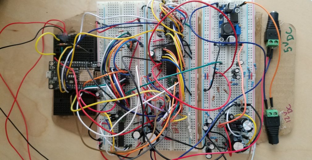
The Brains Behind the Project
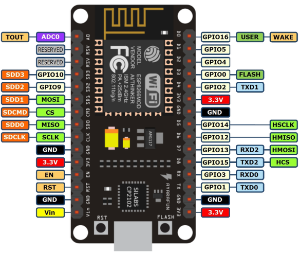
After many different prototypes that all used all sorts of different CPU's, I've finally chosen the ESP8266. Why? It's super speedy (160 MHz!), has an enormous amount of RAM (64k), and even has built-in flash storage for storing video game music files. This eliminates the need for external SD card hardware and simplifies prototyping. I chose to use the NodeMCU 1.0 prototyping board since it contains all of the supporting hardware for the ESP8266 and has a built-in Serial<->UART chip which makes programming a sinch. Oh, and yeah, it has WIFI support if you're into that kind of thing.
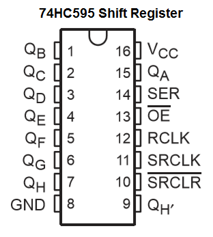
The only downside? The I/O pin count. There are only 8 GPIO (10 without UART) pins available to the programmer. So how in the hell did I manage to drive two chips that require 23 IO in total? Shift Registers. More specifically, 74HC595 serial shift registers.
74HC595 or: How I Learned to Stop Worrying and Love the GPIO
So the ESP8266 definitely has the grunt to drive both of these sound chips, but it certainly doesn't have the I/O. To solve this issue, I deployed three 74HC595 serial shift registers. What do I need all of this I/O for? Mostly data buses, but also, chip control. Both the YM2612 and the SN76489 are old-school chips, meaning that sending data to them is done with a parallel data bus. These data buses, marked on the sound chips as D0-D7, represent 8-bits or 1 byte of data. By toggling specific data pins on and off, we can represent an 8-bit number with binary. A serial shift register will accept one byte of information over a 3-wire serial connection, then spit out that byte as 8-bits over it's 8 output lines (QA-QH). This is perfect, since all we're doing is spitting out bytes to the sound chips and mostly letting them figure out what to do with them. Since both the YM2612 and the SN76489 have 8-bit parallel data pins, each receives it's own dedicated data shift register. Side note, this is kinda' why this project is a little rats-nesty. So. Many. Data lines.
Not only do we need to drive the data buses of both the SN76489 and the YM2612, we also need to operate their control pins. This is where the third shift register comes into play. The "Control Shift Register" shared by both the YM2612 and the SN76489 and only responsible for handling the non-data related control pins on the sound chips. Through a carefully designed function, I can actually control each shift register pin just like generic GPIO.
Like this:
void SetControlReg(byte bitLocation, bool state)
{
    state == HIGH ? controlRegister |= 1 << bitLocation : controlRegister &= ~(1 << bitLocation);
}
The SN76489 PSG only has one pin we need to worry about: Write Enable (WE). You can almost think of WE as a chip select pin. Once WE goes HIGH, the PSG will wait for new data to come in. Once the data has been transfered, we can toggle the WE line LOW, wait a microsecond, then back to HIGH to let the PSG know that the data is ready to be accepted.
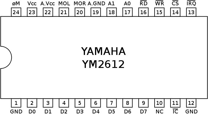
The YM2612 on the other hand has six different control pins that we need to worry about:
- IC: System reset (completely clears all data from the YM2612)
- CS: Chip Select, active LOW
- WR: Write Mode on data bus, active LOW
- RD: Read Mode on Data bus, active LOW
- A0: Read/Write enable, active HIGH
- A1: Part 1 / Part 2 select (LOW for Part 1, HIGH for Part 2)
The YM2612 accepts data in a very strange way due to how the registers are laid out. Usually, a register address is picked first, then the data payload is passed across. If your YM2612 refuses to work, it's probably because one of these control pins are hooked up incorrectly or are being written to in the wrong order. Seriously, these guys are a pain. Not only that, but you need to insure that their initial state is also correct in order for this chip to make any sound at all. You can see the initial state of the registers being set in the "SilenceAllChannels" function in my source code:
void SilenceAllChannels()
{
  SendSNByte(0x9f);
  SendSNByte(0xbf);
  SendSNByte(0xdf);
  SendSNByte(0xff);

  YM_A0(LOW);
  YM_A1(LOW);
  YM_CS(HIGH);
  YM_WR(HIGH);
  YM_RD(HIGH);
  YM_IC(HIGH);
  SendControlReg();
  delay(10);
  YM_IC(LOW);
  SendControlReg();
  delay(10);
  YM_IC(HIGH);
  SendControlReg();
}
Clocking both the SN76489 and the YM2612
Another big challenge was to find a way to clock both the SN76489 and the YM2612. Their seemingly arbitrary clock speeds of 3579545 Hz for the PSG and 7670442 Hz for the YM2612 are actually due to speed of the 53.693175 MHz master clock. 1/15th of 53.693175 MHz of is 3.579545 MHz. 3.58 MHz is the NTSC Colorburst frequency; therefore, due to the abundance of crystals for color TV's at the time, many old computers are clocked at that speed, including the PSG. The YM2612 on the other hand is clocked at 7.670442 MHz, approximately 1/7th of 53.693175 MHz.
Finding crystals for these exactly clock speeds is pretty tough. If you can manage to find a suitable crystal, configuring a pierce oscillator with them is probably the simplest way of driving the clock pin of your target chip. 7.68 MHz and 3.579545 MHz / 3.58 MHz crystals are the easiest to search for. Another solution is to get your hands on a programmable oscillator.
I've picked the LTC6903 SPI programmable oscillator since it can generate a signal between 1Khz and 68 MHz - more than enough for the chips we're driving. Only problem is that they're SOIC surface mount chips, so you will need to pick up SOIC to DIP-8 adapters, but those are very cheap. Just get ready for a pretty annoying solder job. I use two LTC6903's in my project. One for the YM2612 and one for the SN76489 PSG. Both LTC6903's are programmed via SPI from an external PIC16F690 microcontroller, but any MCU with SPI will work (like an Arduino).
If you have chosen to go with an LTC6903, Linear's handy-dandy excel calculator is great for pre-calculating the necessary DAC and OCT values. Picking "6903" at the bottom and plugging in your desired frequency will yield the values to you. It even shows a nifty schematic that I've used in my design too! For those who just want to know the values, they are:
For 7670442 Hz (YM2612):
OCT: 12
DAC: 912
For 3579545 Hz (SN76489):
OCT: 11
DAC: 831
Now, it wont generate those values to an absolute tee, but it will be more than close enough for accurate sound reproduction. Hook up the clock output pin (or inverted clock, it doesn't matter) to the clock input pins of your sound chips and you're good to go! You can see how I program the LTC6903's via SPI in PIC C code compiled with CCS here.
Mixing and Amplification
Another huge challenge of working with the YM2612 and the SN76489 PSG is mixing and amplification. Like I mentioned earlier, the YM2612 and PSG both have output impedances of about 1k Ω, but the PSG is incredibly loud compared to the YM2612 - nearly 27 dB louder! Further still, the PSG is a mono sound source while the YM2612 is stereo. This means that not only do we need to knock the PSG down a few pegs, but we also need to mix the PSG into two audio channels, THEN amplify the final mix. This is done through a network of resistors and capacitors that can be viewed on this project's schematic. Just as an aside, my schematic says to use 51k Ω resistors to mix the PSG into the YM output lines - in my videos, I've replaced these with 3.2k Ω resistors, since I like the PSG to be a little louder.
To amplify my project, I've chosen to use two LM386 mono amplifiers to achieve stereo sound. Forums often suggest the use of an op-amp setup, but I could never get those to sound correct, so I opt'ed for something simpler. The results are incredible and the sound is crystal clear. If your sound is distorted, make sure to use high-pass output filters marked by C16/R12 and C17/R13 on the schematic respectively. You will also need heavy power filtering on your power rails, especially near the power input pins of the YM2612. I recommend large capacitors (1000 uF - 2200 uF) straddled across VCC and GND for this. Reason being that the shift registers induce a lot of electrical noise which is picked up by the sensitive DAC of the YM2612. Without power filtering, you will hear a loud pounding noise in the output. I used a buck converter to supply the LM386's with 9v of power. By the way, if you attempt to directly plug in amplified audio to a computers line-in, the voltage will likely be way too high and the source will be rejected. While developing your project, I suggest using a pair of dedicated speakers or headphones directly connected to you project to reduce the number of obstacles your audio signal needs to reach you.
Parsing out VGM files
Hardware is important, but this entire project is as good as a doorstop if we didn't have any software to drive it. The ESP8266 is responsible for parsing VGM files and sending data where it needs to go. VGM stands for Video Game Music, and is a 44.1 KHz data logging format that captures the raw data headed to the soundchips on video game consoles. To recreate video game music on our own hardware, we need to read through these VGM files and send the data over our shift registers whenever we come across the commands to. We also need to stash away any PCM samples, wait the appropriate amount of time between samples, control PCM playback, looping, AND we need to control the soundchips. If all of this sounds like a lot, then you're right. IT'S A TON! There is quite a bit going on here, and if your parser is off by just one sample, it's very likely that it won't work at all. Therefore, it's imperative that you read the VGM specification and toss some uncompressed VGM files into a hex editor so you can actually understand what's happening.
The most integral part of my software is the enormous main switch statement that breaks down all of the relevant VGM commands. This is where we first look for the command byte, then, depending on which command it is, execute the steps necessary to complete that command according to the VGM specification. You can also see that I cache PCM samples away in their own separate buffer that we can go back to later. Should your processor crash randomly while opening a specific song, it's probably due to your PCM buffer overflowing. Increasing the PCM buffer size may fix this, but don't go too nuts.
There is also a self-filling buffer for generic commands.This command buffer, along with the arrays of precalculated delays, significantly speeds up the playback speed of VGM files. Sadly, it seems as though the shift registers are a little too slow sometimes, so songs with heavy PCM usage may slow down sometimes. Switching to a microcontroller with more direct I/O will be my next step (ESP32, anyone?).
The Schematic and Source Code
I've built this project to save an awesome set of sound chips from going extinct. They sound amazing compared to their lack-luster emulated counterparts and I suggest that anybody who's interesting in a huge electronics challenge to try this for themselves. I've learned so much from this project, so I hope that my long efforts help see you through your own version!

Other Sweet Projects That are Similar to This One
Jarek319's Hardware Genesis VGM Player - A seriously awesome project that served as my go-to documentation when it came to programming and amplification. Seriously go check out this project if you are interested in this sort of thing. Jarek, your help was greatly appreciated :)
Luis Gonzalez' Hardware Genesis VGM Player - Also a big help and graciously provided me with examples of his source code. Sounds great, and makes me feel better about my spaghetti breadboards, haha!
My Iterative Video Journey of the VGM player - A YouTube playlist that shows the gradual improvements of my project once I finally got music out of it.
...And finally, this cute, garbly mess of audio that vaguely represented music. The very first piece of real sound I managed to get out of the YM2612. You have no idea how happy I was when I first heard this.
Impressive. You write very well, my boy.
Chaos Emerald
really impressed with your work, I learned something new about how to use shift registers today :) I will definitely keep this in mind for when I get back to work and have some money to play with again as I’ve been wanting to play around with a ym2612 for a long time now. Also the ym2151 which was used in a few keyboards but also the sharp x68000